Air supply device, air conditioner and air supply method for air conditioner

A technology of air-conditioning equipment and air-supply devices, which is applied in the direction of air-conditioning systems, lighting and heating equipment, and machine operation methods. It can solve problems such as abnormal airflow noise, avoid abnormal noise, improve flow direction, and reduce airflow separation losses. Effect

Active Publication Date: 2019-03-26
GREE ELECTRIC APPLIANCES INC
View PDF6 Cites 0 Cited by
  • Summary
  • Abstract
  • Description
  • Claims
  • Application Information

AI Technical Summary

Problems solved by technology

[0004] However, the inventors of the present invention found that no matter whether there is a baffle in the area of ​​the air outlet, when controlling the operation of the cross-flow blades of one of the fan systems, due to the influence of the pressure difference inside the air ducts of the two fan systems, the other through The airflow blades will automatically run under the drive of the airflow, which will cause the airflow to rotate in the indoor cavity of the air conditioner and cause abnormal noise

Method used


Image

  • Air supply device, air conditioner and air supply method for air conditioner
  • Air supply device, air conditioner and air supply method for air conditioner
  • Air supply device, air conditioner and air supply method for air conditioner

Examples


Embodiment 1

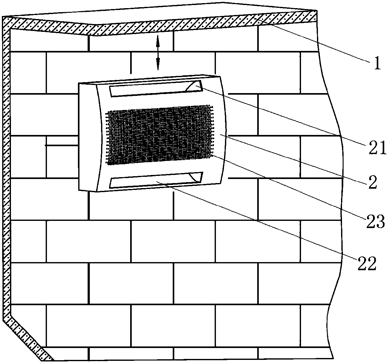
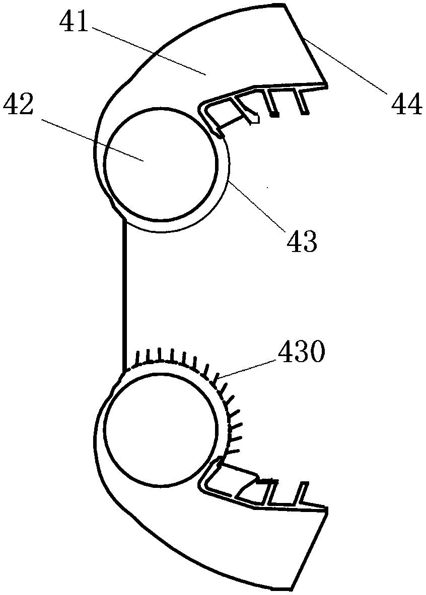
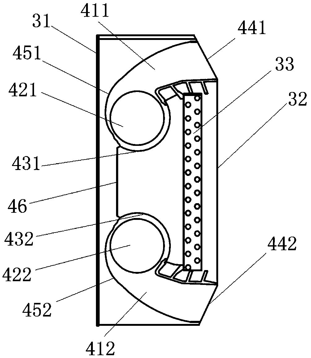
[0052] This embodiment provides an air supply device, the air supply device is used in an air conditioner, and is used to deliver the airflow in the inner chamber of the air conditioner after being heat-exchanged by the heat exchanger to the room. Specifically, such as figure 2As shown, the air supply device includes at least two air duct components. Each air duct assembly includes an air duct 41 , a fan and a guide control device 43 . Wherein, one end of the air duct 41 is configured as an air inlet for allowing the airflow after heat exchange by the heat exchanger to enter the air duct 41 . The other end of the air duct 41 is configured as an air outlet 44 for delivering the airflow entering the air duct 41 to the room. The fan is arranged in the air duct near the air inlet of the air duct 41. On the one hand, under the cooperation of the guide and control device, the air flow after heat exchange enters the air duct 41, and on the other hand, the air flow in the air duct ...

Embodiment 2

[0057] Preferably, if figure 2 As shown, this embodiment provides an air supply device. Compared with the previous embodiment, the guide and control device 43 in this embodiment includes a plurality of deflectors 430 arranged at the air inlet of the air duct 41 . Wherein, when the air duct assembly stops working, the plurality of deflectors 430 included in the guide and control device 43 form a closed door to close the air inlet of the air duct 41 to isolate the air flow from the fans in the air duct 41 . Preferably, the closed door has an arc-shaped structure.

[0058] When the air duct assembly is in the working state, the deflectors 430 of the guide and control device 43 are spaced from each other (that is, there is a gap for the passage of air between any adjacent two deflectors 430), and each The deflectors 430 guide the airflow after heat exchange by the heat exchanger, so that it enters the air duct 41 . in, figure 2 The dotted line in indicates the corresponding p...

Embodiment 3

[0063] Preferably, this embodiment provides an air supply device, compared with the above embodiments, such as figure 2 As shown, the fan includes a first motor and fan blades 42, and the fan blades 42 in this embodiment are preferably cross-flow fan blades. The guiding and controlling device 43 also includes a second motor for driving the deflector 430 to rotate.

[0064] Preferably, the first motor and the second motor are the same motor. By setting in this way, the working states of the fan and the pilot control device 43 can be well synchronized. That is, as long as the fan of the air duct assembly stops running, the pilot control device 43 will close the air duct of the air duct assembly.

[0065] Preferably, the guide and control device in this embodiment further includes a connecting rod (not shown in the figure), and a plurality of deflectors are arranged on the connecting rod and can rotate relative to the connecting rod. When the air duct assembly stops working, ...


PUM


Abstract

The invention relates to an air supply apparatus, air conditioning equipment and an air supply method of the air conditioning equipment, and relates to the technical field of an air conditioner. The invention mainly adopts the technical scheme that the air supply apparatus comprises at least two air duct assemblies, wherein each air duct assembly comprises an air duct, a fan and a guidance and control apparatus. One end of each air duct is arranged as an air inlet, and the other end of the air duct is arranged as an air outlet; the fans are arranged at the positions, which are close to the air inlets, in the air ducts; the guidance and control apparatuses are arranged at the positions of the air inlets of the air ducts. When the air duct assemblies work, the guidance and control apparatuses enable air flow subjected to heat exchange by a heat exchanger to be led into the air ducts from the air inlets. When the air duct assemblies stop working, the guidance and control apparatuses seal the air inlets of the air ducts. The air conditioning equipment comprises the air supply apparatus. The air supply method of the air conditioning equipment is characterized by adopting the air conditioning equipment to deliver the air flow subjected to heat exchange by the heat exchanger into a room. The air supply apparatus, the air conditioning equipment and the air supply method of the air conditioning equipment, which are disclosed by the invention, are mainly used for avoiding the condition that the air flow in an inner cavity of the air conditioning equipment disturbs fan blades of fans in a work stop state to cause generation of abnormal noise.

Description

technical field [0001] The invention relates to the technical field of air conditioning, in particular to an air supply device, air conditioner and an air supply method for the air conditioner. Background technique [0002] Currently, double cross-flow air conditioning equipment has two fan systems for supplying air. Specifically, such as figure 1 As shown, the double cross-flow air conditioner 2 is provided with an upper air outlet 21, a lower air outlet 22 and an air inlet 23; wherein, the upper air outlet 21 and the lower air outlet 22 are respectively located on the upper side and the lower side of the air inlet 23; and the upper The distance between the air outlet 21 , the lower air outlet 22 and the air inlet 23 is relatively short; after the double cross-flow air conditioner is installed, the upper air outlet 21 is located near the ceiling 1 . When the double cross-flow air conditioner is cooling, because the airflow pressure difference between the air inlet 23 and ...

Claims


Application Information

Patent Timeline
Patent Type & Authority Patents(China)
IPC IPC(8): F24F1/00F24F1/0025F25B29/00F24F13/06
CPCF24F1/0014F24F1/0025F24F13/06F25B29/00
Inventor 黄美玲邹建煌张苏北刘中杰曹雷
Owner GREE ELECTRIC APPLIANCES INC
Why Eureka
Try Eureka