Partition control blasting method for tunnel rock drilling project

A partition control and engineering technology, applied in blasting and other directions, can solve the problems of weak drilling and blasting control, increase the amount of charge in the same section of the cutting hole, increase the amount of charge in the hole, etc., and achieve control of the distance of blasting flying stones, Reduce the negative effects of blasting and reduce the effect of blasting vibration

Active Publication Date: 2016-05-25
坚兵(北京)工程技术有限公司
View PDF7 Cites 11 Cited by
  • Summary
  • Abstract
  • Description
  • Claims
  • Application Information

AI Technical Summary

Problems solved by technology

At the same time, the drilling and blasting control of the traditional rock drilling section is weak. When the blasting is started, the blasting stress between the blasting holes will cancel and interfere with each other, resulting in the inability to exert the power of the blasting explosives and low blasting efficiency. The negative effects of blasting such as stress failure and disturbance are relatively large, especially when the geology of the rock drilling section is relatively complicated, it may cause serious consequences
[0003] In addition, the traditional wedge-shaped drilling and blasting method is a construction method that is relatively easy to grasp and has unive

Method used


Image

  • Partition control blasting method for tunnel rock drilling project
  • Partition control blasting method for tunnel rock drilling project
  • Partition control blasting method for tunnel rock drilling project

Examples


Embodiment 1

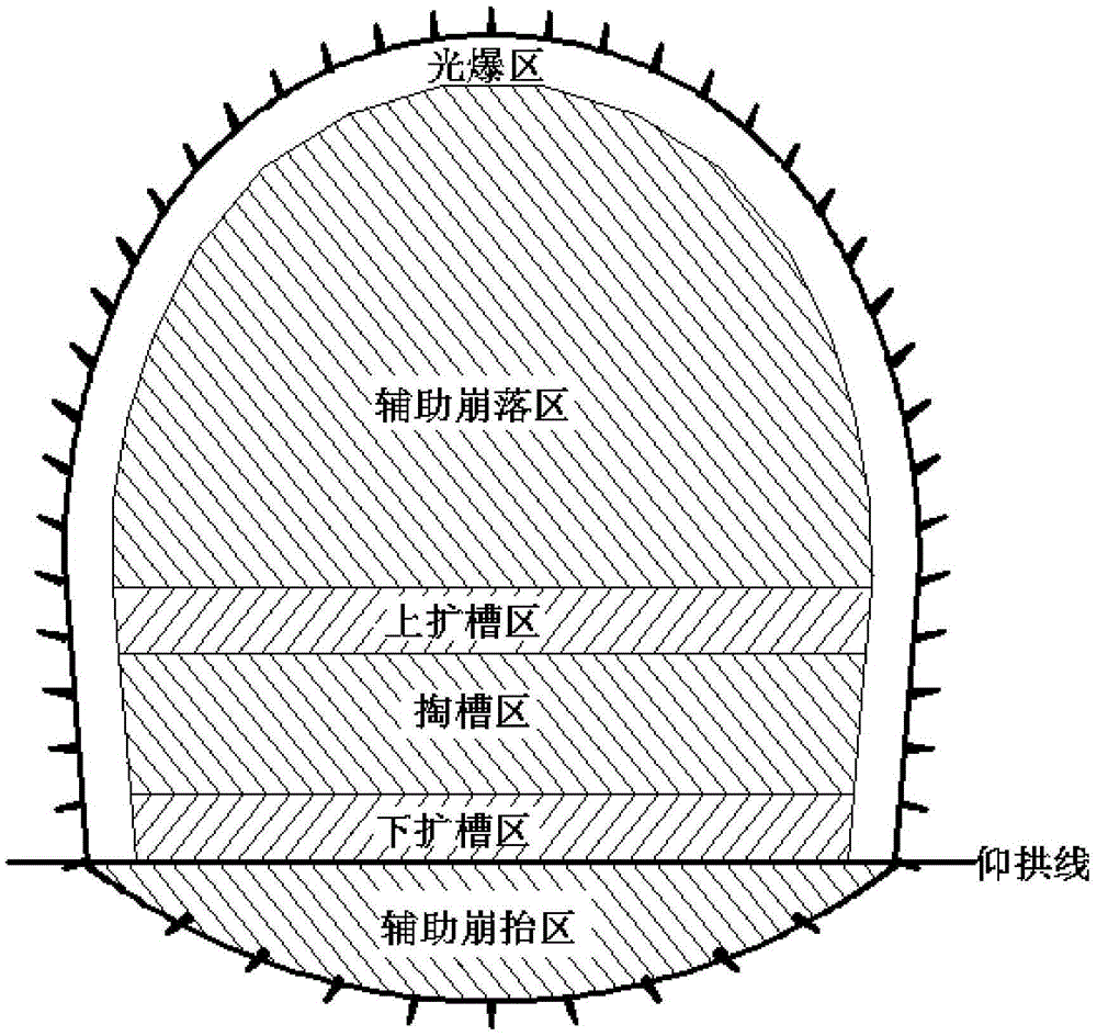
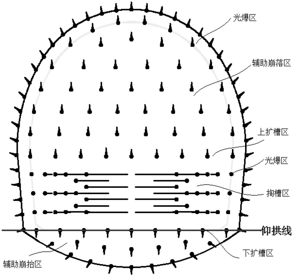
[0031] refer to figure 2 , 3 As shown, a tunnel rock drilling engineering partition control blasting method, the steps are as follows:

[0032] 1) Partitioned drilling: Divide the rock drilling face into the cutting area, the upper and lower expansion areas, the auxiliary caving area, the auxiliary caving area and the light explosion area, and drill holes in each area;

[0033] The lower middle area of ​​the rock drilling face is the cutting area, which is composed of 3-4 rows and more than 10 rows of symmetrical horizontally inclined blastholes. The value of the resistance line between the holes is 75cm, the height of the cut is 1.5m, and the row spacing between the blastholes in the cut area is 400-750mm;

[0034] The upper and lower areas of the cutting area of ​​the rock drilling face are the upper and lower expansion areas. The upper and lower expansion areas are the connection areas between the blastholes in the cutting area and the blastholes in the auxiliary caving ...

Embodiment 2

[0044] like figure 2 , 4 As shown, this embodiment is basically the same as Embodiment 1, and the difference is that it is applicable to high-speed rail double lines. like Figure 4 As shown, the schematic diagram of the layout of the blastholes on the double-line section of the high-speed railway, the cutout area is composed of 3 rows and 14 rows of horizontally inclined blastholes that are left and right symmetrical.


PUM


Abstract

The invention discloses a partition control blasting method for a tunnel rock drilling project. The partition control blasting method sequentially comprises the steps that a rock drilling working surface is partitioned into a slotting partition, an upper and down slot expanding partition, an auxiliary collapsing partition, an auxiliary collapse lifting partition and a light blasting partition, and all the partitions are drilled to form holes; the blast holes are filled with explosives; rock drilling section blasting is started; the slotting partition and the upper and down slot expanding partition are blasted; then the auxiliary collapse lifting partition is blasted; the auxiliary collapsing partition is blasted; finally the light blasting partition is blasted. The partition control blasting method is a project blasting method used for underground rock drilling projects with large sections and has the advantages that the blasting vibration can be controlled, and the blasting effect can be improved.

Description

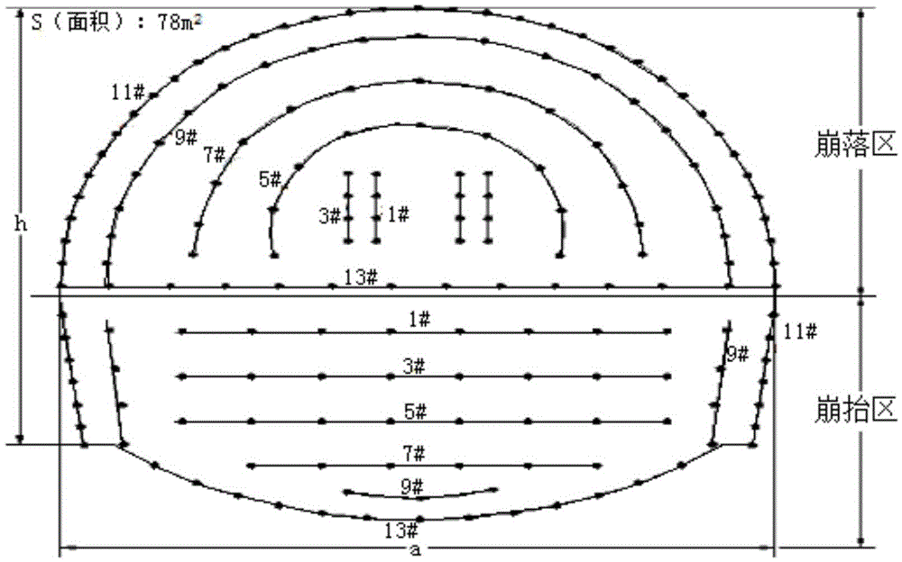
technical field [0001] The invention relates to an engineering blasting method used in underground large-section rock drilling engineering, capable of controlling blasting vibration and improving blasting effect. Background technique [0002] like figure 1 As shown, in the traditional drilling and blasting method, the caving and avalanche areas during blasting are basically the same, each accounting for 1 / 2 of the drilling section. At the same time, the drilling and blasting control of the traditional rock drilling section is weak. When the blasting is started, the blasting stress between the blasting holes will cancel and interfere with each other, resulting in the inability to exert the power of the blasting explosives and low blasting efficiency. The negative effects of blasting such as stress failure and disturbance are relatively large, especially when the geology of the rock drilling section is relatively complicated, it may cause serious consequences. [0003] In ad...

Claims


Application Information

Patent Timeline
IPC IPC(8): F42D1/08F42D3/04
CPCF42D1/08F42D3/04
Inventor 何仕宁张文建秦诚信
Owner 坚兵(北京)工程技术有限公司
Why Eureka
Try Eureka