

Mechanical width detection unit and appearance detector
A width detection and mechanical technology, applied in the field of logistics, can solve the problems of high cost, high cost of photoelectric tubes, cumbersome detection process control, etc., and achieve the effect of low cost, simple operation and high detection accuracy
- Summary
- Abstract
- Description
- Claims
- Application Information
AI Technical Summary
Problems solved by technology
Method used
Image

Examples
Embodiment 1
[0031] Embodiment 1: as Figure 4 As shown, a shape detection device includes a main mounting frame 1, two mechanical width detection units 2 arranged on the main mounting frame 1, and a photoelectric switch installed on the mechanical width detection unit 2 The photoelectric switch mounting bracket 3.
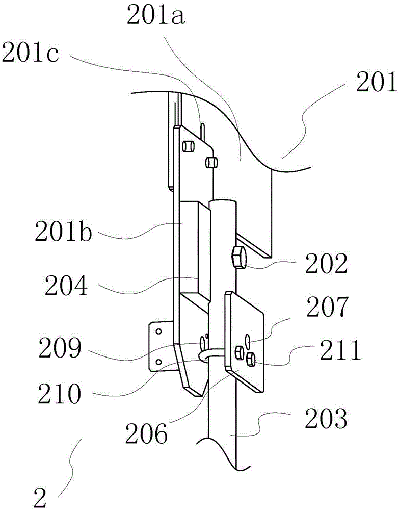
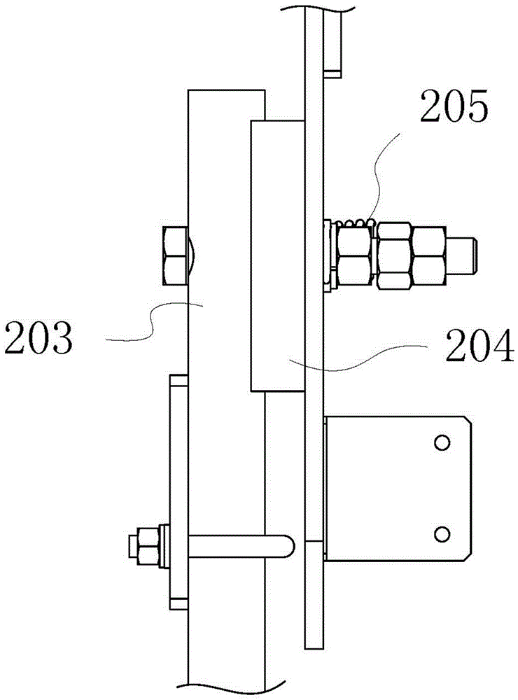
[0032] like figure 2 and 3 As shown, the mechanical width detection unit 2 includes an installation base 201, a detection striker 203 hinged on the installation base 201, a limiter 204 for limiting the rotation of the detection striker 203, and a detection striker for the detection. 203 applies the elastic force portion 205 of the radial elastic force and the light shielding plate 206 with the light-transmitting hole 207 on the detection rod 203; the elastic force portion 205 and the detection rod 203 are located at the installation base 201 on the same side. The mounting base 201 includes a mounting base 201a and a mounting block 201b disposed on the mounting base 201a; ...
Embodiment 2
[0035] Embodiment 2: A shape detection device, including a main mounting frame 1, two mechanical width detection units 2 arranged on the main mounting frame 1, and a photoelectric sensor installed on the mechanical width detection unit 2 The photoelectric switch installation frame 3 of switch.
[0036] The mechanical width detection unit 2 includes an installation base 201, a detection striker 203 hinged on the installation base 201, a limiter 204 for limiting the rotation of the detection striker 203, and a diameter applied to the detection striker 203. The elastic force part 205 to the elastic force and the light shielding plate 206 with the light-transmitting hole 207 arranged on the detection rod 203; side. The mounting base 201 includes a mounting substrate 201a and a mounting block 201b disposed on the mounting substrate 201a.
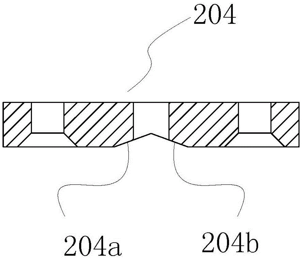
[0037] The limiting portion 204 is disposed on the mounting block 201b; includes a limiting groove, and the limiting groove is an arc surface;...
Embodiment 3
[0039] Embodiment 3: A shape detection device, including a main mounting frame 1, two mechanical width detection units 2 arranged on the main mounting frame 1, and two mechanical width detection units 2 arranged on the mechanical width detection unit 2 for installing photoelectric The photoelectric switch installation frame 3 of switch.
[0040] The mechanical width detection unit 2 includes an installation base 201, a detection striker 203 hinged on the installation base 201, a stopper 204 for limiting the rotation of the detection striker 203, and a diameter applied to the detection striker 203. The elastic force portion 205 of the elastic force and the light shielding plate 206 with the light-transmitting hole 207 arranged on the detection striker 203; the elastic force portion 205 and the detection striker 203 are located on the same side of the installation base 201 . The limiting portion 204 is disposed on the installation base 201 .
[0041] The limiting portion 204 i...
PUM
 Abstract
Description
Claims
Application Information