
Main busbar lapping device and method of low-voltage distribution cabinet

A busbar overlapping and power distribution cabinet technology, which is applied in the directions of busbar/line layout, substation/switch layout details, electrical components, etc., can solve problems affecting production efficiency, packaging and transportation quality, and long installation time, so as to improve packaging The effect of transportation quality, convenient combination of cabinets and convenient installation

Active Publication Date: 2016-05-25
NANJING DAQO ELECTRIC CO LTD
View PDF4 Cites 3 Cited by
  • Summary
  • Abstract
  • Description
  • Claims
  • Application Information

AI Technical Summary

Problems solved by technology

[0002] In the traditional domestic low-voltage cabinet busbar system, when the cabinets are overlapped, one side of the busbar protrudes out of the cabinet, and the other side shrinks into the cabinet, resulting in the dimensions of the shipping package and the box being wider than the size of the cabinet. , when shipping and packing, it is necessary to fill the gap between the packing box and the cabinet, which seriously affects the production efficiency and the quality of packaging and transportation
In addition, after the cabinets are delivered to the customer's site, the main busbars of the traditional low-voltage cabinets protrude / extrude out of the cabinets. When combining the cabinets, the main busbars must be dislocated and overlapped first. The position of the cabinets needs to be adjusted many times, and the on-site installation takes a long time.

Method used


Image

  • Main busbar lapping device and method of low-voltage distribution cabinet
  • Main busbar lapping device and method of low-voltage distribution cabinet
  • Main busbar lapping device and method of low-voltage distribution cabinet

Examples


Embodiment

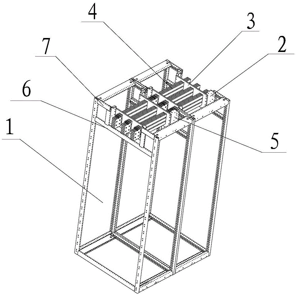
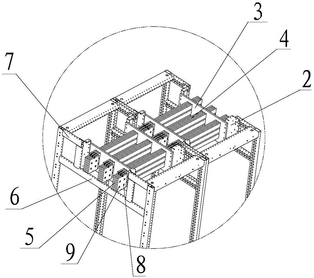
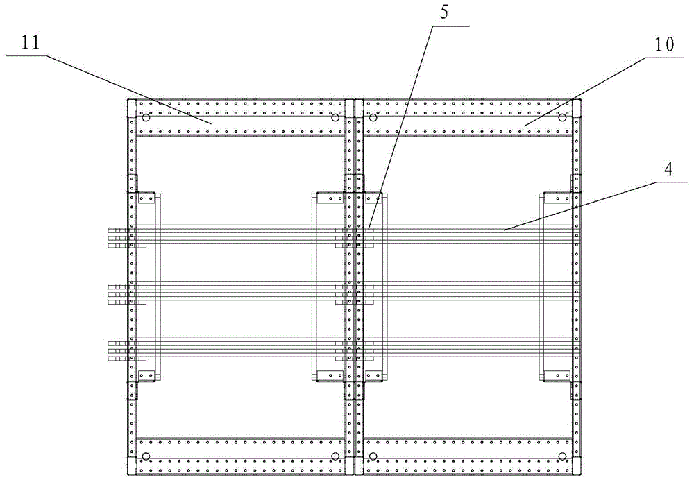
[0021] The structure of this embodiment is as Figure 1-Figure 4 As shown, the main busbar lapping device of the low-voltage power distribution cabinet includes two main frames 1 and the main busbar 4 installed on the top of the main frame. Horizontal support rods 6 are symmetrically arranged on both sides of the top, and the two ends of the support rods 6 near the main frame 1 are provided with a fixed plate 2 perpendicular to the support rods 6, and one side of the fixed plate 2 is in the same plane as the surface of the support rods 6. The other side of the plate 2 extends into the main frame 1, the fixed plate 2 is connected to the main frame 1 through the fixed rod 7, the other side of the fixed plate 2 is connected to the epoxy resin plate 3, and the main busbar is passed through the epoxy resin plate 3 4. The end face of the main busbar 4 is fixedly overlapped with the connecting row 5 . The outer side of the overlapping connecting row 5 protrudes from the plane where ...


PUM


Abstract

The invention relates to a lapping device and method of a distribution cabinet, particularly to a main busbar lapping device and method of a low-voltage distribution cabinet, belonging to the technical field of electric equipment. The device structurally comprises at least one main framework and main busbars arranged at the top of the main framework, wherein the main framework is a cuboid structure assembled of C-shaped stand columns; lateral bracing rods are symmetrically arranged at two sides of the top of the main framework; fixed plates are arranged at two ends, close to the main framework, of the bracing rods and are vertical to the bracing rods, one sides of the fixed plates are in the same plane with the surfaces of the bracing rods; the other sides of the fixed plates extend into the main framework; the fixed plates are connected with the main framework through fixing rods; the other sides of the fixed plates are connected with epoxy resin plates through which the main busbars penetrate, and lapping connection bars are fixed at the end faces of the main busbars. The lapping device and method have the advantage of improving the packaging transportation quality, which brings users great convenience for the field installation.

Description

technical field [0001] The invention relates to a lapping device and a lapping method of a power distribution cabinet, in particular to a lapping device and a lapping method for main busbars of a low-voltage power distribution cabinet, and belongs to the technical field of electrical equipment. Background technique [0002] In the traditional domestic low-voltage cabinet busbar system, when the cabinets are overlapped, one side of the busbar protrudes out of the cabinet, and the other side shrinks into the cabinet, resulting in the dimensions of the shipping package and the box being wider than the size of the cabinet. , When shipping and packing, it is necessary to fill the gap between the packing box and the cabinet, which seriously affects the production efficiency and the quality of packaging and transportation. In addition, after the cabinets are delivered to the customer's site, the main busbars of the traditional low-voltage cabinets protrude / extrude out of the cabine...

Claims


Application Information

Patent Timeline
Patent Type & Authority Applications(China)
IPC IPC(8): H02B1/20H02B1/01
CPCH02B1/013H02B1/20
Inventor 杨如由谢静唐林梁玉斌江福勇
Owner NANJING DAQO ELECTRIC CO LTD
Learn More