Dual-mode detector pixel, uncooled infrared detector and use method thereof

An uncooled infrared and detector technology, used in radiation pyrometry, instruments, measuring devices, etc., can solve problems such as increasing production costs and use costs, reduce manufacturing costs and use costs, expand the scope of application, reduce The effect of the type of specification

Active Publication Date: 2021-08-13
武汉鲲鹏微纳光电有限公司
View PDF6 Cites 0 Cited by
  • Summary
  • Abstract
  • Description
  • Claims
  • Application Information

AI Technical Summary

Problems solved by technology

Different application places have different requirements for uncooled infrared detectors. For example, in some special places, uncooled infrared detectors are required to have large area arrays, small pixel imaging, and clearer resolution; Increased production cost and use cost

Method used


Image

  • Dual-mode detector pixel, uncooled infrared detector and use method thereof
  • Dual-mode detector pixel, uncooled infrared detector and use method thereof
  • Dual-mode detector pixel, uncooled infrared detector and use method thereof

Examples


Embodiment 1

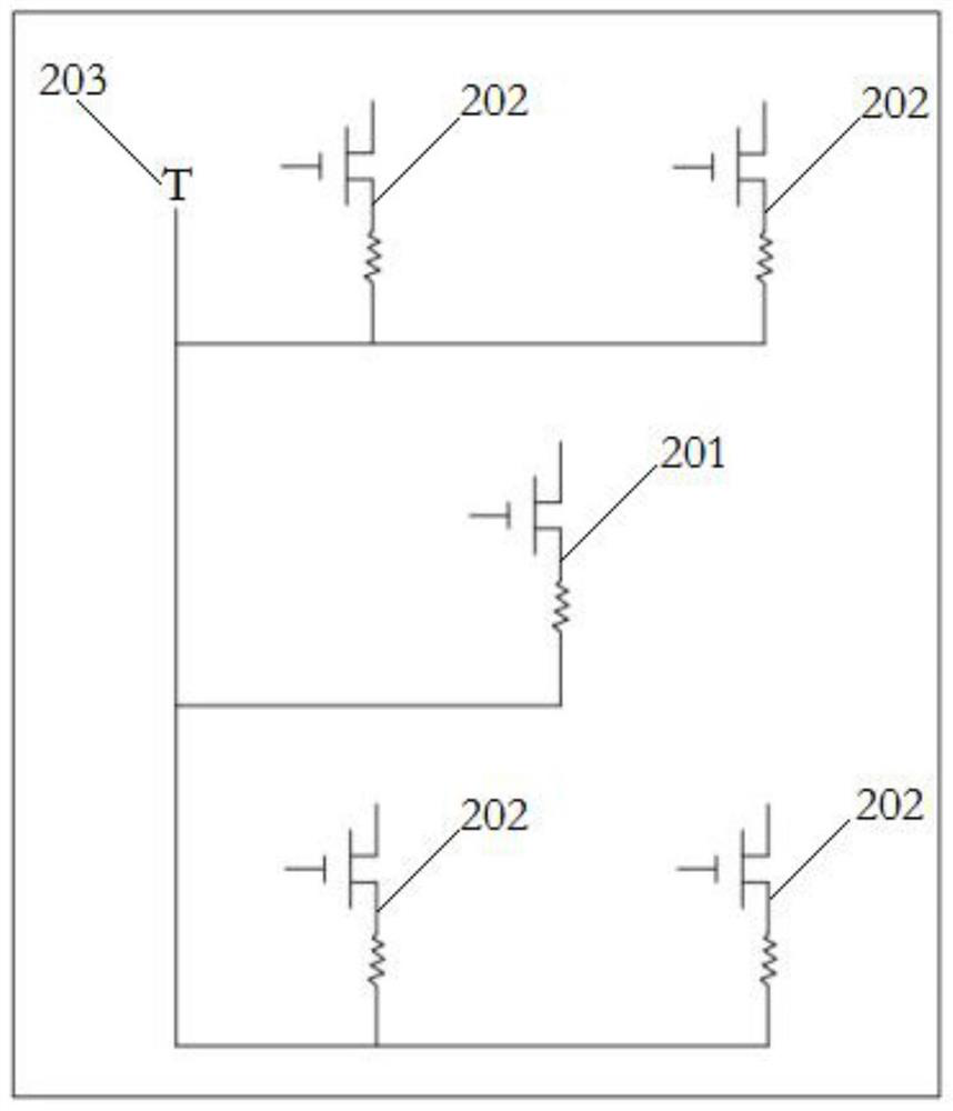
[0020] like figure 1 , an embodiment of the present invention provides a dual-mode detector pixel sharing a readout circuit, including a dual-mode bridge deck layer, a substrate, and a dual-mode readout circuit arranged on the substrate, and the dual-mode readout circuit includes Each is equipped with a first branch 201 and four second branches 202 of control switches. The four corners of the dual-mode bridge deck layer lead out from the side bridge legs and lead out from the center bridge leg in the center of the bridge deck. , wherein, the first shunt 201 is electrically connected to the two opposite side bridge legs, and the four second shunts 202 are all electrically connected to the central bridge leg and are in one-to-one correspondence with the four side bridge legs electrical connection.

[0021] The structures of the bridge deck layer, the substrate and the bridge legs are conventional technologies in the field, and will not be repeated here.

[0022] The above-ment...

Embodiment 2

[0027] An embodiment of the present invention provides an uncooled infrared detector, which includes a plurality of detector pixels arranged in an array, and at least some of the detector pixels use the dual-mode detector pixels that share the readout circuit provided in the first embodiment above. Wherein, preferably, each detector pixel uses the dual-mode detector pixel.

[0028] The embodiment of the present invention also provides a method for using the above-mentioned uncooled infrared detector, including:

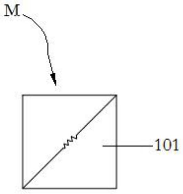
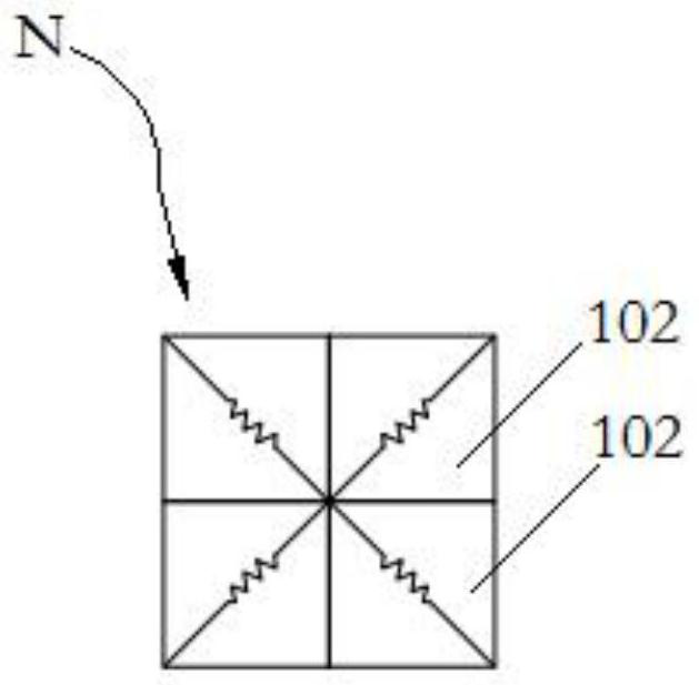
[0029] Select the uncooled infrared detector to work in the first mode M or the second mode N according to the working conditions,

[0030] In the first mode M, in each dual-mode detector pixel, the first branch 201 is controlled to work and each second branch 202 is disconnected;

[0031] In the second mode N, in each dual-mode detector pixel, the first branch 201 is controlled to be disconnected and the second branch 202 is controlled to work.


PUM


Abstract

The invention relates to a dual-mode detector pixel sharing a readout circuit. The pixel comprises a dual-mode bridge floor layer, a substrate and a dual-mode readout circuit arranged on the substrate. The dual-mode readout circuit comprises a first branch and four second branches which are respectively provided with a control switch; and the four corners of the dual-mode bridge floor layer extend out of edge bridge legs respectively, a center bridge leg extends out of the center of the bridge floor, the first branch is electrically connected with the two opposite edge bridge legs, and the four second branches are electrically connected with the center bridge leg and electrically connected with the four edge bridge legs in a one-to-one correspondence mode. In addition, the invention also relates to an uncooled infrared detector adopting the dual-mode detector pixel and a use method of the uncooled infrared detector. Through the special design of the readout circuit, the same readout circuit can realize two imaging working modes with different array sizes and different pixel sizes, the application range of the pixel and the detector is effectively expanded, the specification types of the detector can be reduced, and the preparation cost and the use cost are decreased.

Description

technical field [0001] The invention relates to a dual-mode detector pixel unit sharing a readout circuit, a non-cooling infrared detector using the dual-mode detector pixel unit and a method for using the non-cooling infrared detector. Background technique [0002] Infrared detectors are widely used in the fields of security, national defense and health care. It is divided into cooled infrared detectors and uncooled infrared detectors. Among them, uncooled infrared detectors are Low-level advantages are more and more widely used; at present, uncooled infrared detectors are not only widely used in national defense and military fields, but also in civilian fields. Different application places have different requirements for uncooled infrared detectors. For example, in some special places, uncooled infrared detectors are required to have large area arrays, small pixel imaging, and clearer resolution; Increased production costs and use costs. Contents of the invention [00...

Claims


Application Information

Patent Timeline
IPC IPC(8): G01J5/00
CPCG01J5/00G01J2005/0077
Inventor 蔡光艳黄立马占锋汪超王春水高健飞
Owner 武汉鲲鹏微纳光电有限公司
Why Eureka
Try Eureka