Eureka AIR delivers breakthrough ideas for toughest innovation challenges, trusted by R&D personnel around the world.

Mobile terminal

A technology of mobile terminals and waterproof membranes, which is applied to the structure of telephones, sensors, electrical components, etc., and can solve problems such as misalignment, deflection, tilt, and movement between conductive shrapnel and flexible cables

Active Publication Date: 2016-05-25
QINGDAO HISENSE MOBILE COMM TECH CO LTD
View PDF4 Cites 42 Cited by
  • Summary
  • Abstract
  • Description
  • Claims
  • Application Information

AI Technical Summary

Problems solved by technology

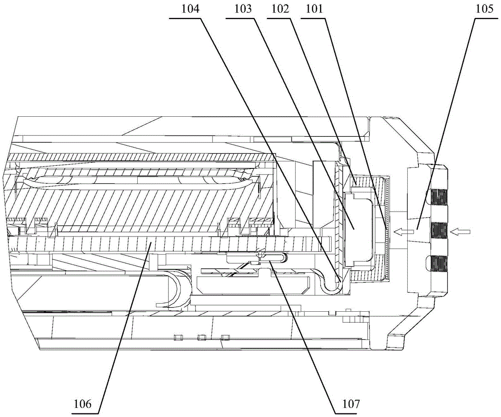
[0004] However, the sealing and waterproof structure of the microphone in the prior art has the following deficiencies: First, because the internal space of the mobile terminal housing is small and difficult to assemble, and the inside of the waterproof membrane is in contact with the silicone sleeve on the outside of the microphone, when pasting the waterproof membrane, It is easy to cause uneven sealing and wrinkles due to improper assembly. When the microphone is loose, it may further cause the waterproof membrane to wrinkle or slip, affecting the waterproof sealing effect of the microphone
Secondly, because the microphone and the circuit board are connected by a flexible cable, when the microphone is assembled, deflection, inclination, etc. are likely to be improperly assembled due to the length limitation of the flexible cable, which affects the sealing consistency, and the flexible cable and the conductive The shrapnel is easy to move due to the displacement of the microphone itself, resulting in dislocation or disconnection of the connection between the conductive shrapnel and the flexible cable
This is prone to poor contact or sound leakage, which will affect the sound signal collection effect of the microphone.

Method used


Image

  • Mobile terminal
  • Mobile terminal
  • Mobile terminal

Examples


Embodiment Construction

[0020] In order to make the purpose, technical solutions and advantages of the embodiments of the present invention clearer, the technical solutions in the embodiments of the present invention will be clearly and completely described below in conjunction with the drawings in the embodiments of the present invention. Obviously, the described embodiments It is a part of embodiments of the present invention, but not all embodiments. Based on the embodiments of the present invention, all other embodiments obtained by persons of ordinary skill in the art without making creative efforts belong to the protection scope of the present invention.

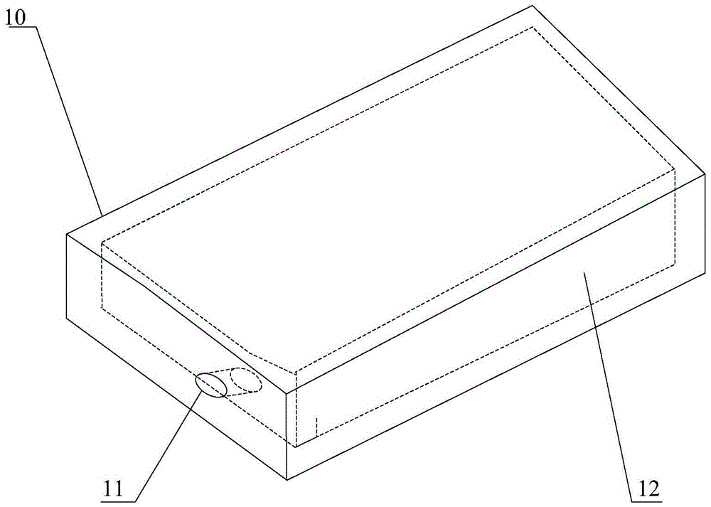
[0021] Figure 2A It is a schematic structural diagram of a mobile terminal provided in Embodiment 1 of the present invention. Such as Figure 2A As shown, the mobile terminal described in this embodiment includes a housing 10, the housing 10 is usually a closed structure, and the housing 10 is provided with a sound pickup hole 11, and the ...


PUM


Abstract

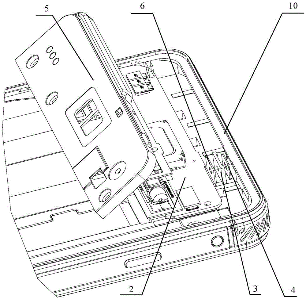
The invention provides a mobile terminal. The mobile terminal provided by the invention comprises a shell; a pickup hole is formed in the shell; a microphone, a circuit board, a waterproof membrane bracket, a waterproof membrane and a sound receiving bracket are arranged in the inner cavity of the shell; the waterproof membrane is stuck on the waterproof membrane bracket and is supported against the pickup hole which is located at the inner sidewall of the shell; the microphone is arranged on the circuit board; a sound receiving through hole which is opposite to the waterproof membrane is formed in the waterproof membrane bracket; the sound receiving bracket is connected with the shell; the sound receiving bracket is provided with a through hole; one end of the through hole is opposite to the sound receiving through hole of the waterproof membrane bracket while the other end thereof is opposite to the receiving end of the microphone, so that a sound conduction channel is formed between the pickup hole and the receiving end of the microphone; and the circuit board is electrically connected with the microphone to drive the microphone to receive sound. According to the mobile terminal, a microphone sealing and waterproof structure with good sealing and high reliability can be realized.

Description

technical field [0001] The present invention relates to mobile terminal technology, in particular to a mobile terminal. Background technique [0002] At present, with the popularity of mobile terminals such as mobile phones, more and more attention has been paid to the three-proof (dustproof, waterproof, drop-proof) performance of mobile terminals. Among them, the waterproof performance of mobile terminals such as mobile phones has always been one of the focuses. [0003] At present, the outer shells of mobile terminals such as mobile phones are integrally sealed, and the shells are provided with key grooves, sound pickup holes for microphones to pick up sound, and the like. Among them, the sound pickup hole of the microphone is located at the end of the mobile phone casing, and is generally a through hole that runs through the inside and outside of the mobile phone casing. Usually, a microphone waterproof structure is provided to perform waterproof and sealing treatment o...

Claims


Application Information

Patent Timeline
Patent Type & Authority Applications(China)
IPC IPC(8): H04M1/03H04M1/04H04R1/08
CPCH04M1/03H04M1/04H04R1/083
Inventor 李传顺刘晓飞张新服
Owner QINGDAO HISENSE MOBILE COMM TECH CO LTD
Why Eureka
Eureka Blog
Learn More