Main oil seal demounting tool provided with handle sleeve and used for remanufacturing of automatic transmission

A technology for automatic transmissions and removal tools, applied in the manufacture of tools, hand-held tools, etc., can solve the problem that the main oil seal cannot be reused, and achieve the effect of reducing remanufacturing costs and improving convenience

Active Publication Date: 2016-06-01
TAIZHOU HAILING HYDRAULIC MACHINERY
View PDF6 Cites 3 Cited by
  • Summary
  • Abstract
  • Description
  • Claims
  • Application Information

AI Technical Summary

Problems solved by technology

[0003] The invention provides a main oil seal dismantling tool provided with a handle glove for automatic transmission remanufacturing which can completely disassemble the main oil seal, which solves the problem that the main oil seal can only be broken and taken off during the remanufacturing process of the automatic transmission. The main oil seal cannot be reused

Method used


Image

  • Main oil seal demounting tool provided with handle sleeve and used for remanufacturing of automatic transmission
  • Main oil seal demounting tool provided with handle sleeve and used for remanufacturing of automatic transmission
  • Main oil seal demounting tool provided with handle sleeve and used for remanufacturing of automatic transmission

Examples


Embodiment 1

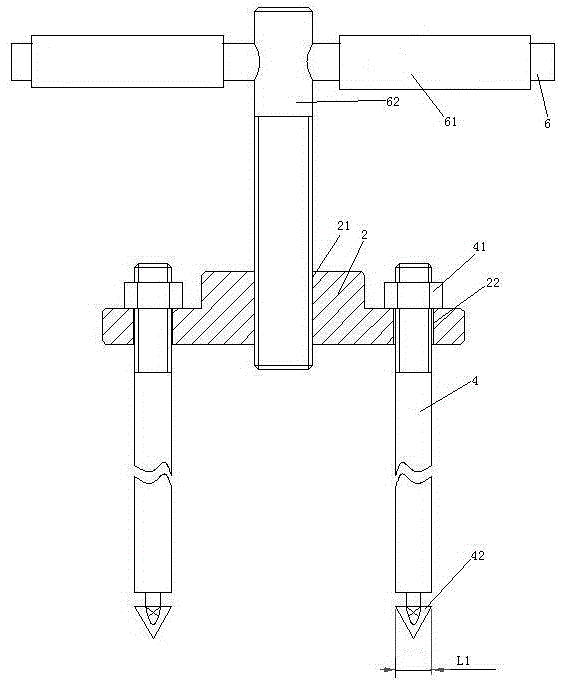
[0028] Embodiment one, see figure 2 , a main oil seal removal tool provided with a handle for automatic transmission remanufacturing, including a base 2, a gripping rod 6 and a pull rod 4.

[0029] A threaded hole 21 is provided in the middle of the base 2 . The threaded hole 21 runs through the base 2 . The base 2 is also provided with two optical holes 22 symmetrically distributed on both sides of the threaded hole.

[0030]Grip bar 6 has two. The two holding rods 6 are located on the same straight line and have an integral structure. 6 sets of grip bars are provided with handle gloves 61 . The handle glove 61 is a rubber sheath. One end of a connecting rod 62 is provided at the junction of the two holding rods 6 . The two holding rods 6 and the connecting rod 62 are connected together in a T-shape. The other end of the connecting rod 62 is provided with a threaded section and is threaded into the threaded hole 21 .

[0031] Pull bar 4 has two. The extension direct...

Embodiment 2

[0034] Embodiment two, the difference with embodiment one is;

[0035] see Figure 4 , also includes motor 5. The motor 5 includes a motor housing 51 and a motor shaft 52 . The motor housing 51 is fixedly connected with the base 2 through the support rod 53 . The motor casing 51 is provided with the connection terminal 3 . One end of the motor shaft 52 is connected to the connecting rod 62 through the reducer 54 . The grip bar 6 is connected to the other end of the motor shaft 52 .

[0036] see Figure 5 , An elastic adjustment mechanism 8 is provided between the grip bar 6 and the handle cover 61 . The elastic force adjustment mechanism 8 includes a base pipe 81 , a clamping layer 82 and a preload adjustment structure 83 . The base pipe 81 is sheathed outside the handle bar 6 . The base pipe 81 is passed through the handle glove 61 . The clamping layer 82 is composed of several friction strips 821 . The friction strips 821 are distributed along the circumferential d...


PUM


Abstract

The invention relates to the technical field of automatic transmissions. A main oil seal demounting tool provided with a handle sleeve and used for remanufacturing of an automatic transmission comprises a base, a handheld rod and two pull rods used for penetrating into two inner cavities in a one-to-one correspondence manner. The handheld rod and the base are connected together through a connecting rod. One end of each pull rod is rotationally connected to the base in a hooking manner, and the other end of each pull rod is provided with a hook head, wherein the length of the hook heads is smaller than that of an opening but larger than the width of the opening, and the width of the hook heads is smaller than that of the opening. The handheld rod is provided with the handle sleeve. A threaded hole penetrating the base in the extending direction of the pull rods is formed in the base. The connecting rod is in threaded connection into the threaded hole. The two pull rods are symmetrically distributed on the two sides of the connecting rod. The main oil seal demounting tool provided with the handle sleeve and used for remanufacturing of the automatic transmission can be used for completely demounting a main oil seal, and the problem that the main oil seal can be taken down only after being broken in the remanufacturing process of the automatic transmission, and consequently the main oil seal cannot be reused is solved.

Description

technical field [0001] The invention relates to the technical field of automatic transmission remanufacturing, in particular to a main oil seal dismantling tool provided with a handle glove for automatic transmission remanufacturing. Background technique [0002] The main oil seal is a part of the input clutch of the automatic transmission. The structure of the main oil seal is as follows: figure 1 As shown, two inner cavities 11 are arranged on the end surface of the main oil seal 1 , the inner cavities 11 are symmetrically distributed on both radial sides of the main oil seal 1 , and the inner cavities 11 are provided with elongated openings 12 . It is sometimes necessary to remove the main oil seal from the automatic transmission during rebuilding of the automatic transmission. The existing way to disassemble the main oil seal is to break the main oil seal and remove it in pieces, which makes the removed main oil seal unusable and increases the remanufacturing cost of th...

Claims


Application Information

Patent Timeline
Patent Type & Authority Applications(China)
IPC IPC(8): B25B27/00
CPCB25B27/0028
Inventor 何子玉
Owner TAIZHOU HAILING HYDRAULIC MACHINERY
Why Eureka
Try Eureka