Lipped oil seal installation tool with grip bar for automatic transmission remanufacturing

A technology for automatic transmission and tool installation, which is applied in the manufacture of tools and hand-held tools, etc. It can solve the problems of inconvenient installation of oil seals with lips, and achieve the effect of reducing remanufacturing costs

Active Publication Date: 2017-11-28
HANGZHOU TENGHUA AUTOMOTIVE TRANSMISSION
View PDF6 Cites 0 Cited by
  • Summary
  • Abstract
  • Description
  • Claims
  • Application Information

AI Technical Summary

Problems solved by technology

[0003] The invention provides an oil seal installation tool with a lip for conveniently installing the oil seal with a lip on the remanufacturing automatic transmission, which is provided with a grip bar, and solves the problem of installing the lip with a lip during the remanufacturing process of the automatic transmission. The problem of inconvenient oil seal

Method used


Image

  • Lipped oil seal installation tool with grip bar for automatic transmission remanufacturing
  • Lipped oil seal installation tool with grip bar for automatic transmission remanufacturing
  • Lipped oil seal installation tool with grip bar for automatic transmission remanufacturing

Examples


Embodiment 1

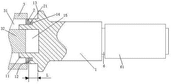
[0029] Embodiment one, see figure 1 , a lipped oil seal installation tool provided with a grip bar for remanufacturing an automatic transmission, comprising a push rod 1 . The push rod 1 extends in the left-right direction. The left end of the push rod 1 is provided with a column head 11 , a first protruding ring 12 and a second protruding ring 13 in sequence. An escape hole 15 is provided on the end surface of the column head 11 . An annular groove 14 for accommodating the lip is formed on the end surface of the first protruding ring 12 . The right end of the push rod 1 is provided with a grip bar 6 . 6 sets of grip bars are provided with handle gloves 61 . The handle glove 61 is a rubber sheath.

[0030] The oil seal 2 is provided with a lip 21 . The diameter of the column head 11 is smaller than the inner diameter of the oil seal 2 . The outer diameter of the first protruding ring 12 is smaller than or equal to the outer diameter of the oil seal 2 (in this embodiment...

Embodiment 2

[0035] Embodiment two, the difference with embodiment one is;

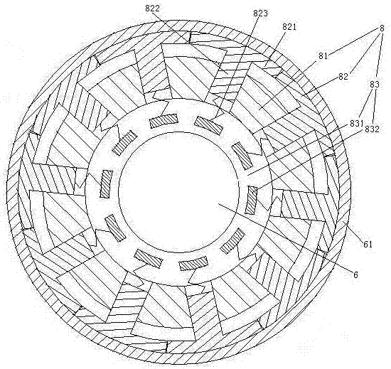
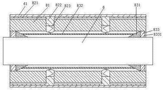
[0036] see Figure 4 , The push rod 1 is also provided with an oil seal dismounting booster mechanism 9. The oil seal detachment assisting mechanism 9 includes a fan 91 , an air duct 92 and an air direction conversion mechanism 93 . The fan 91 is provided with an air inlet 911 and an air outlet 912 . The fan 91 includes fan blades 913 and a motor 914 for driving the fan blades. The air duct 92 is an annular structure. The air duct 92 communicates with the air inlet 911 and the air outlet 912 . The air duct 92 is provided with an entrance and exit passage 921 , an entrance passage 922 and an exit passage 923 . The entrance and exit passage 921 passes through the annular groove 14 on the first protrusion ring 12 . The entrance and exit passage 921 is provided with an annular cylinder 924 extending along the circumference of the column head 11 . The annular cylinder body 924 is sealed and slidably connected wi...


PUM


Abstract

The invention relates to the technical field of remanufacturing of an automatic gearbox, in particular to a mounting tool with a holding rod for an oil seal with a lip side for remanufacturing of the automatic gearbox. The mounting tool comprises a push rod; one end of the push rod is sequentially provided with a column head, a first convex ring and a second convex ring; the diameter of the column head is smaller than the inner diameter of the oil seal; the outer diameter of the first convex ring is smaller than or equal to the outer diameter of the oil seal; an annular groove containing the lip side is formed in the end face of the first convex ring; the outer diameter of the second convex ring is larger than the outer diameter of the oil seal; the distance between the first convex ring and the second convex ring is equal to the depth that the oil seal needs to be mounted inside a part for mounting the oil seal of the gearbox; the other end of the push rod is provided with the holding rod, and a receding hole for containing a shaft head in a hole of the part for mounting the oil seal of the gearbox is formed in the end face of the column head. The mounting tool with the holding rod for the oil seal with the lip side for remanufacturing of the automatic gearbox can mount the oil seal with the lip side conveniently, and the problem that the oil seal with the lip side is inconvenient to mount in the remanufacturing process of the automatic gearbox is solved.

Description

technical field [0001] The invention relates to the technical field of remanufacturing of automatic transmissions, in particular to a lipped oil seal installation tool provided with a grip bar for automatic transmission remanufacturing. Background technique [0002] Oil seals with lips are installed in the transmission's oil pump, differential cover, left half shaft and other components. The above oil seals with lips need to be installed in the corresponding parts during the rebuilding process of the automatic transmission. The existing way of installing the above oil seal is to align the oil seal with the hole of the part where the oil seal is installed by hand, and then press or tap the oil seal with a hammer to install the oil seal. This method is very inconvenient to install and the oil seal is difficult to install. The required depth, and it is easy to cause local deformation of the oil seal and the shaft head in the hole of the parts where the oil seal is installed in...

Claims


Application Information

Patent Timeline
Patent Type & Authority Patents(China)
IPC IPC(8): B25B27/02
CPCB25B27/02
Inventor 何子军
Owner HANGZHOU TENGHUA AUTOMOTIVE TRANSMISSION
Why Eureka
Try Eureka