Check patentability & draft patents in minutes with Patsnap Eureka AI!

3D printer with temperature control function

A 3D printer and printing table technology, applied in the field of 3D printing, can solve the problems of easy clogging of the print head and poor heat dissipation effect, so as to improve the printing efficiency, prevent clogging and improve the printing quality.

Inactive Publication Date: 2016-06-01
CHENGDU MEILYU SCI & TECH CO LTD
View PDF0 Cites 2 Cited by
  • Summary
  • Abstract
  • Description
  • Claims
  • Application Information

AI Technical Summary

Problems solved by technology

[0003] The purpose of the present invention is: in order to solve the above problems, the present invention proposes a 3D printer with temperature control, in order to solve the problems of poor heat dissipation and easy blockage of the printing head in the prior art.

Method used


Image

  • 3D printer with temperature control function

Examples


Embodiment Construction

[0010] In order to make the object, technical solution and advantages of the present invention clearer, the present invention will be further described in detail below in conjunction with the accompanying drawings and embodiments. It should be understood that the specific embodiments described here are only used to explain the present invention, not to limit the present invention.

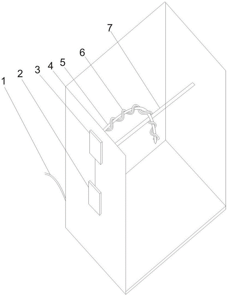
[0011] Such as figure 1 Shown is a schematic structural view of the 3D printer of the present invention. The 3D printer with temperature control of the present invention includes a printing table unit 4 and a printing head unit 5, a guide rod 7 is arranged inside the printing table unit 4, a bearing table is arranged at the bottom of the printing head unit 5, and the printing table unit 5 is provided with a bearing table. The head unit 5 includes an ink delivery tube and a print head, and also includes a control unit 2, a cooling unit 1, a power unit 3 and a temperature control unit 6. The control...


PUM


Abstract

The invention discloses a 3D printer with a temperature control function. The 3D printer with the temperature control function comprises a printing table unit and a printing head unit and further comprises a cooling unit, a control unit, a power unit and a temperature control unit. The control unit and the power unit are located on the side wall of the printing table unit. The control unit is connected with the power unit. The cooling unit is located at the bottom of a bearing table. The cooling unit is an S-shaped one-way pipe. The temperature control unit is a two-way communicating pipe and is wound outside a printing ink delivery pipe of a printing head. According to the 3D printer with the temperature control function, the temperature of ink in the printing head unit is controlled through the temperature control unit, so that the printing quality is improved, and the printing head is prevented from being blocked; a printed article is cooled through the cooling unit, so that the printing quality and the printing efficiency are improved.

Description

technical field [0001] The invention belongs to the technical field of 3D printing, and in particular relates to a 3D printer with temperature control. Background technique [0002] Existing engineering models, such as architectural models, are generally made by hand using iron wire or plastic lap joints, which requires a lot of manpower and material resources. Especially for some architectural models with complex structures and special nodes, more man-hours are consumed, and the assembled architectural models are unstable and easy to collapse. In addition, for relatively fine architectural models, handmade is difficult to achieve. Existing engineering models, such as architectural models, are generally made by hand using iron wire or plastic lap joints, which requires a lot of manpower and material resources. Especially for some architectural models with complex structures and special nodes, more man-hours are consumed, and the assembled architectural models are unstable ...

Claims


Application Information

Patent Timeline
IPC IPC(8): B29C67/00B22F3/00B28B1/00B22F12/00B22F12/13B22F12/20B22F12/53B22F12/90
Inventor 不公告发明人
Owner CHENGDU MEILYU SCI & TECH CO LTD
Features
  • R&D
  • Intellectual Property
  • Life Sciences
  • Materials
  • Tech Scout
  • Unparalleled Data Quality
  • Higher Quality Content
  • 60% Fewer Hallucinations
Learn More