Eureka AIR delivers breakthrough ideas for toughest innovation challenges, trusted by R&D personnel around the world.

Track turnout structure

A turnout and track technology, applied in the field of track turnout structure, can solve the problems of interval iron bolt shearing, bolt shearing, affecting normal work, etc., to avoid frequent damage, reduce shear force, and simple structure

Inactive Publication Date: 2016-06-01
WUHU CRSIC JIFU RAIL CO LTD
View PDF6 Cites 2 Cited by
  • Summary
  • Abstract
  • Description
  • Claims
  • Application Information

AI Technical Summary

Problems solved by technology

However, in the movable center track switch, the front end of the long center rail and the end of the wing rail are both in a free state; the two are connected by spacer iron; because the rail is affected by temperature changes, a temperature force will be generated inside it, and the center rail and the wing rail are in a free state. The wing rail will produce lateral dislocation movement; during the movement process, the interval iron bolts connecting the two will usually be sheared due to the large shear force; in addition, during the driving process, the wheel will also produce lateral movement to the rail. Both the impact force and the longitudinal shear force will shear the bolts. When the vehicle is driving or the temperature difference changes greatly, it is even very easy to shear the bolts, which will affect the normal work.

Method used


Image

  • Track turnout structure
  • Track turnout structure
  • Track turnout structure

Examples


Embodiment Construction

[0020] Below with reference to the accompanying drawings, through the description of the embodiments, the specific embodiments of the present invention, such as the shape, structure, mutual position and connection relationship between the various parts, the role and working principle of the various parts, etc., will be further described. Detailed instructions:

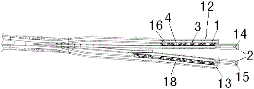
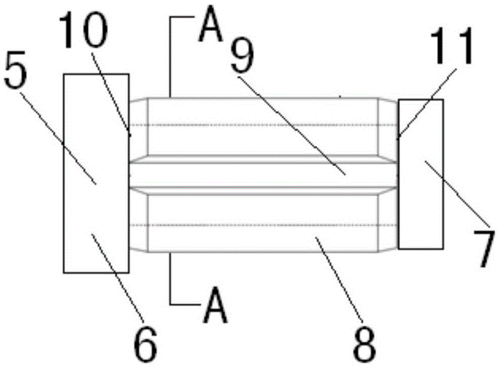
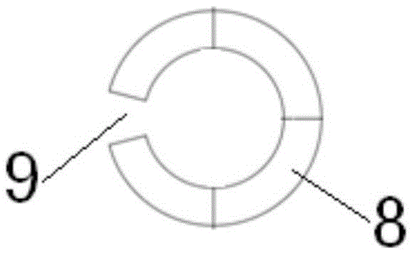
[0021] as attached figure 1 — attached Figure 4 As shown, the present invention is a track turnout structure, the track turnout structure includes wing rail 1, core rail 2, wing rail 1 and core rail 2 are connected by spacer iron 3, and the spacer iron 3 includes spacer Iron body 4, connecting assembly 5, connecting assembly 5 includes connecting bolt 6, connecting nut 7, connecting bolt 6 is set to be able to pass through the structure of wing rail 1, spacer iron body 4, core rail 2 in sequence, connecting nut 7 and the structure that pass through successively The connecting bolts 6 of the wing rail 1, the spacer i...


PUM


Abstract

The invention provides a track turnout structure.Interval iron (3) of the track turnout structure comprises an interval iron body (4) and a connecting assembly (5) which comprises a connecting bolt (6) and a connecting nut (7), wherein the connecting bolt (6) is designed into a structure of sequentially penetrating through wing rails (1), the interval iron body (4) and point rails (2), the connecting nut (7) is in screwed connection with the connecting bolt (6) which sequentially penetrates through the wing rails (1), the interval iron body (3) and the point rails (2), and the connecting bolt (6) is sleeved with a damping sleeve (8) which is of a sleeve structure.The track turnout structure is simple and capable of buffering and decomposing shear force produced by interaction between the point rails and the wing rails during stress, shear force on the connecting bolt of the interval iron is greatly reduced, the risk that the connecting bolt is shorn is effectively reduced, the replacement period is shortened, and cost is saved.

Description

technical field [0001] The invention relates to a track switch structure. Background technique [0002] The existence of harmful spaces in ordinary track switches limits the speed of trains passing through track switches, which is very unfavorable for trains that need to run at high speeds. Therefore, the movable center track switch is designed according to the needs. The most important feature of the movable center track switch is that the long center rail of the frog can be moved. When opening a track in a certain direction, the frog long center rail of the movable center rail is closely attached to the wing rail with the same opening direction, and is separated from the other wing rail. In this way, the harmful space of the common turnout does not exist. The moveable track switch eliminates the harmful space of the switch, makes the driving more stable, and the speed limit of the vehicle passing the frog is small. However, in the movable center track switch, the front ...

Claims


Application Information

Patent Timeline
Patent Type & Authority Applications(China)
IPC IPC(8): E01B7/14
CPCE01B7/14
Inventor 钱世山曹宗石闫忠杰赵振华王力红吴义伟
Owner WUHU CRSIC JIFU RAIL CO LTD
Why Eureka
Eureka Blog
Learn More