
Patsnap Eureka
For R&D, Patsnap Eureka makes reading and utilizing patents & technical documents easy.
Patsnap Eureka AIR
Designed for self-driven R&D workflows. Generate viable solutions, solve complex R&D challenges, empower your innovation with AI.

Patsnap Eureka Materials
Designed for material experts only. Revolutionize your material R&D, from search, analyze, to developing new materials.

TechResearch
Generate reliable direction feasibility study reports for your R&D in just a few steps.

TechSeek
Discover and master advanced knowledge NOW. Basics, ideas, possibilities, all at once.

TechMind
As an expert in R&D Theories, TechMind can generates customized viable solutions instantly.

TechRisk
Analyze your overall solution with one click, know your potential R&D risks in advance.

TechMonitor
Get weekly tech updates, stay abreast of the latest tech innovations and key insights.
Fin ring bearing mechanism and punch forming device with same
A fin ring and fin technology, applied in the field of stamping and forming devices, can solve the problems of high defective rate and scrap rate, reduced finger flexibility and sensitivity, low efficiency, etc. Reduced risk of cuts and improved work efficiency
- Summary
- Abstract
- Description
- Claims
- Application Information
AI Technical Summary
Problems solved by technology
Method used
Image

Examples
Embodiment 1
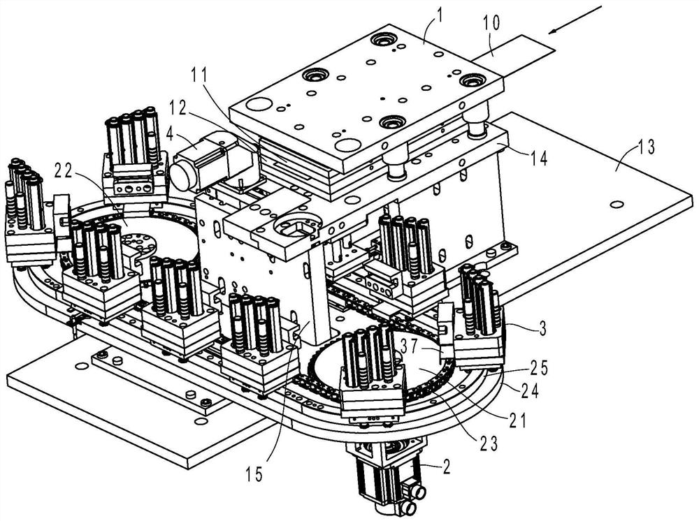
[0038] Example 1, such as image 3 with Figure 4 As shown, the fin ring stamping and forming device in this embodiment includes a body 1, a stamping head 112, a stamping die and a fin ring receiving mechanism, combined with Image 6 with Figure 7 As shown, the stamping head 112 is arranged on the machine body 1 so that it can move up and down. There is a discharge port 122 in the stamping die. A die cutting knife 121 is provided on the discharge port 122. The inner cavity of the die cutting knife 121 is adapted to the fin ring. . The body 1 is provided with a waste material punch 111 and a forming punch 114, and the stamping die includes an upper template 11, a lower template 12, an upper shaping assembly 124 arranged on the upper template 11, and a lower shaping assembly 113 arranged on the lower template 12. The template 12 has a discharge hole 123 for waste discharge and a discharge port for the fin ring to drop. The discharge hole 123 is located directly below the was...
Embodiment 2
[0045] Example 2, such as Figure 9 with Figure 10 As shown, the lifting mechanism 4 in this embodiment includes a vertically arranged lifting cylinder 45 and a connecting plate 43 located at the bottom end of the lifting cylinder 45. The connecting plate 43 is detachably connected with the receiving plate 32. The lifting cylinder in this embodiment 45 is located on the mounting plate. Refer to Example 1 for other structures.
PUM
 Abstract
Description
Claims
Application Information
 - R&D Engineer
- R&D Manager
- IP Professional
- Industry Leading Data Capabilities
- Powerful AI technology
- Patent DNA Extraction
Browse by: Latest US Patents, China's latest patents, Technical Efficacy Thesaurus, Application Domain, Technology Topic, Popular Technical Reports.
© 2024 PatSnap. All rights reserved.Legal|Privacy policy|Modern Slavery Act Transparency Statement|Sitemap|About US| Contact US: help@patsnap.com