
Full-automatic laser marking device for engine cylinder ring
An engine cylinder and laser marking technology, which is applied in auxiliary devices, laser welding equipment, auxiliary welding equipment, etc., can solve problems affecting production efficiency and increasing human resource input costs, and achieve simple structure, solve human resource input, and automation high degree of effect
Patent Information
- Authority / Receiving Office
- CN · China
- Current Assignee / Owner
- Publication Date
- 2019-06-18
Smart Images
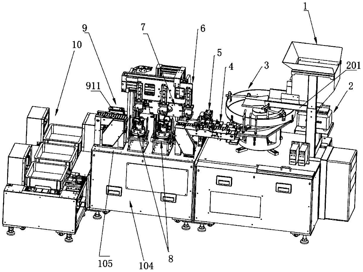
Figure 1 
Figure 2 
Figure 3
Abstract
Description
technical field
[0001] The invention relates to the field of mechanical automation equipment, in particular to a fully automatic laser marking device for engine cylinder rings. Background technique
[0002] The engine cylinder ring is an essential engine accessory in the automotive field. At present, in order to realize the marking on the outer circumference of the engine cylinder ring, the loading, unloading and marking of the cylinder ring are all done manually. In order to avoid the wrong direction of the cylinder ring marking, it is also done by Manually flipping the cylinder ring, this manual operation method increases the human resource input cost of the enterprise, increases the labor intensity of the workers, and seriously affects the production efficiency of the enterprise. Contents of the invention
[0003] In view of the above existing problems, the applicant has carried out research and improvement, and provides a fully automatic laser marking device for engine...
Examples
Embodiment Construction
[0067] Specific embodiments of the present invention will be described below.
[0068] Such as figure 1 , figure 2 As shown, the fully automatic laser marking device for the cylinder ring of the engine is composed of a feeding mechanism, an executing mechanism and a feeding mechanism 10 arranged in sequence;
[0069] Such as Figure 1 to Figure 5 As shown, the feeding mechanism includes a first welding frame 101 with an electric control cabinet 102, a first worktable 103 is arranged on the first welding frame 101, and a vibrating feeder is arranged on the first worktable 103 2. The discharge tray 201 is arranged on the surface of the vibrating feeder 2, the feed end of the discharge tray 201 is docked with the discharge port of the hopper 1, and the discharge end of the discharge tray 201 is docked with the disc body of the vibration plate 3;
[0070] The executive mechanism includes a second welding frame 104 and a cover assembly 11. A second worktable 105 is arranged on ...