Nuclear facility pool cleaning equipment

A technology for cleaning equipment and nuclear facilities, applied in nuclear engineering, nuclear power generation, nuclear reactor monitoring, etc., can solve the problem of limited accessibility at the edge of the pool, and achieve the effect of simplifying the construction or assembly, and simply dispatching floating platforms

Active Publication Date: 2020-08-21
WESTINGHOUSE ELECTRIC GERMANY
View PDF6 Cites 0 Cited by
  • Summary
  • Abstract
  • Description
  • Claims
  • Application Information

AI Technical Summary

Problems solved by technology

A disadvantage in this respect is the relatively large width of the nuclear plant pool, for example 20m to 30m, which necessitates truck cranes or gantry cranes traveling on rails with correspondingly large spans
Furthermore, pool edge accessibility is very limited by local conditions, e.g. by adjoining buildings or existing gantry cranes

Method used


Image

  • Nuclear facility pool cleaning equipment
  • Nuclear facility pool cleaning equipment
  • Nuclear facility pool cleaning equipment

Examples


Embodiment Construction

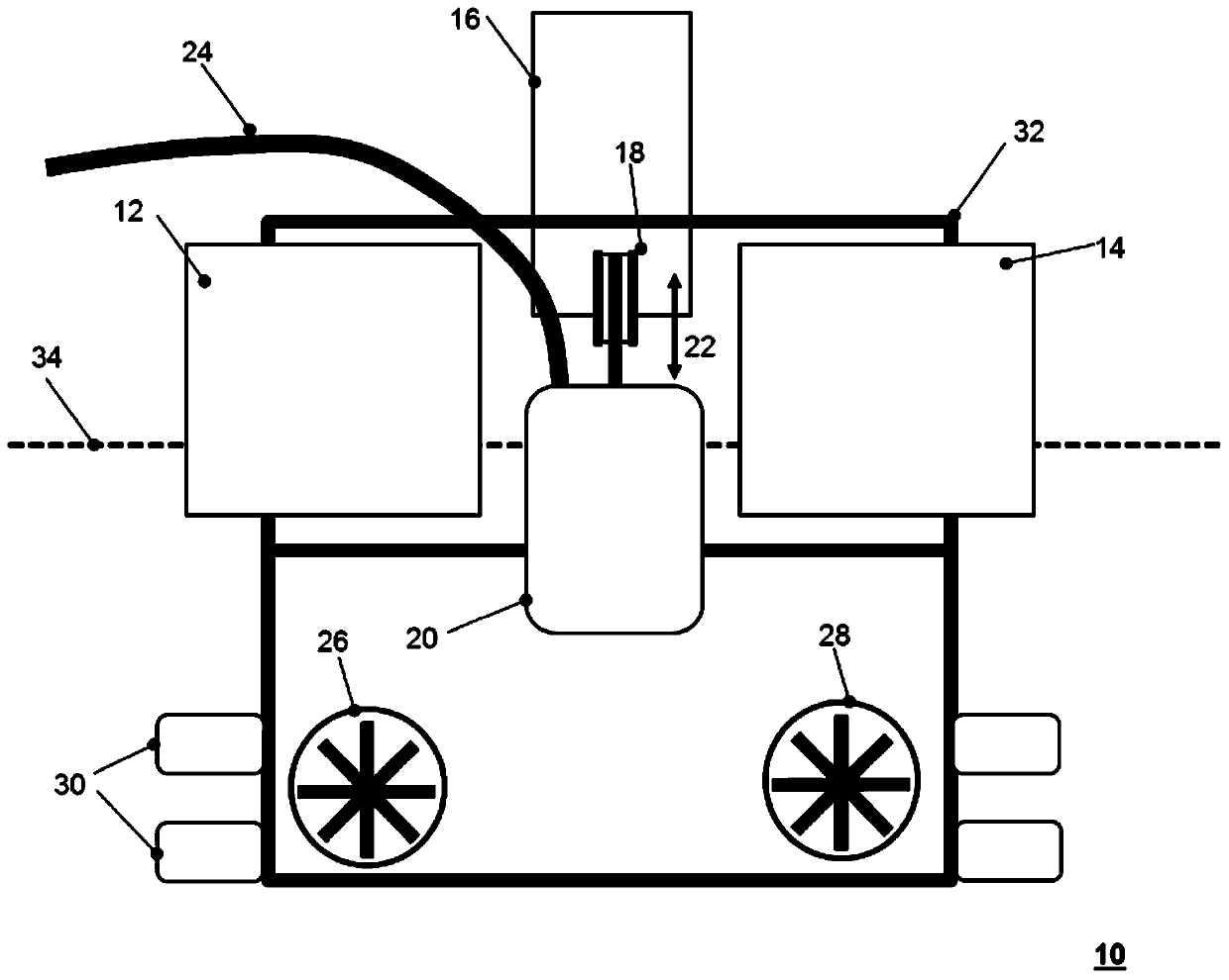
[0036] figure 1 A first example floating platform 10 is shown in side view. At the metal frame 32 , cuboid floating bodies 12 , 14 are arranged on both sides of its axial center, and these floating bodies keep the floating platform 10 floating in the water at least partially above the water surface 34 . Between the buoys 12 , 14 arranged at a distance relative to each other, a towing device 16 is provided, in this case comprising a winch with a drive, which can be moved by a rope guided via a winch wheel 18 . The pump 20 fixed at the end of the rope is hoisted up or down in the direction of the arrow 22 . The pump 20 is connected via a suction hose 24 to a storage tank, not shown, into which the pumped water is introduced.

[0037]The floating platform 10 can be fully adjusted by means of a drive device comprising a plurality of drives 26 , 28 , which, like the towing device 16 , can be remotely controlled via a remote control device (not shown). Partially surrounding dampe...


PUM


Abstract

The invention relates to a nuclear facility pool cleaning equipment, comprising: a floating platform (10, 40, 62) capable of floating in water (80) with a buoyant body (12, 14, 46, 48); The drive equipment (26,28) that moves the floating platform (10,40,62) on the surface of the nuclear facility pool (78) to be cleaned; the towing equipment (16) connected with the floating platform (10,40,62) , 54); the pump (20, 52, 66) that can be vertically hoisted up and down (22) by towing equipment (16, 54), the pump has a first end connected thereto for cleaning nuclear facilities Suction hoses (24, 70) for the bottom of the pool (78); remote control equipment (86) for at least remote driving equipment (26, 28) and towing equipment (16, 54); optional fixed external A storage tank ( 76 ), wherein the suction hose ( 24 , 70 ) preferably leads at least indirectly with its second end into the fixed external storage tank ( 76 ).

Description

technical field [0001] The invention relates to a nuclear facility pool cleaning equipment. It is known that burnt spent fuel is temporarily temporarily stored in nuclear facilities where nuclear reactions are carried out, such as nuclear power plants. Such storage is usually done in pools of water or in nuclear facility pools, or outdoors outside buildings, depending on local conditions. Background technique [0002] Owing to the unavoidable ingress of organic particles such as leaves, dirt, dust or the like outdoors, sludge-like deposits accumulate over time in pools of such nuclear facilities. The sludge consists mostly of organic material and a small portion of highly radioactive fuel particles. Temporary storage of spent fuel is usually stored in storage containers of the trough dump type made of steel plates, which are in themselves indeterminate locations in the pool of nuclear facilities. Suspended matter in the water limits the view into the pool making visual po...

Claims


Application Information

Patent Timeline
Patent Type & Authority Patents(China)
IPC IPC(8): E02F3/88E02F3/92
CPCE02F3/8833E02F3/9256G21F9/28G21F9/34G21C19/32G21C19/07Y02E30/30B01D21/2477E02F3/8866G21C17/01
Inventor 托马斯·施特罗迈尔多米尼克·德姆特勒德乌多·魏因特拉格
Owner WESTINGHOUSE ELECTRIC GERMANY
Why Eureka
Try Eureka