Universal supporting combined frame supporting unit and universal supporting combined frame

A technology of support unit and combined frame, which is applied in the direction of house structure support, house structure support, construction, etc., can solve the problems of waste of labor, inconvenient handling, inflexibility, etc., and achieves reduction of production cost, simple and reasonable design, and convenient height adjustment. Effect

Inactive Publication Date: 2016-06-01
广西建工第五建筑工程集团有限公司
View PDF15 Cites 5 Cited by
  • Summary
  • Abstract
  • Description
  • Claims
  • Application Information

AI Technical Summary

Problems solved by technology

[0002] Traditional support systems and operating platforms usually use fasteners to connect rods. The operation is complicated. Due to the quality of fasteners and unforeseen factors, local rods often slip or even collapse, making it difficult to guarantee safety and stability.
At the same time, the existing support frame is very dangerous to be demolished, and it is inconvenient to assemble and use. Its components are too long, inconvenient to transport, slow to assemble, and its low efficiency takes up a lot of construction time on the construction site and delays the construction progress.
In addition, the commonly used support frames for building high-rise buildings and bridges still have the following disadvantages: a large number of manual transportation is required from the unloading point to the erection point; Handling wastes a lot of labor, the erection process takes a long time, the erection process is unsafe, and the steel pipe scaffolding is expensive; the secondary disassembly after pouring the concrete is very troublesome, wasting labor and a lot of time, and the on-site dismantling environment is harsh; a large number of scaffolding steel pipes push It is not easy to arrange; the construction process of using steel pipes is complicated, and the elevation of the entire surface can only be adjusted after the steel pipes and wood are erected, wasting a lot of steel pipes, wood and labor; according to the specifications, steel pipes and two small pieces are required between each jacking and formwork Formwork filling and adding square strips waste a lot of manpower and material resources. Workers do not add them in many places for convenience, causing great safety hazards
But there are still the following disadvantages: the adjustable height range of the support frame is small, the height of each support unit is fixed, and only the base can be adjusted in a small range, which is not suitable for high-altitude operations, and there are many components, complex structure, single combination form, not flexible enough, and occupying an area The area is large, the firmness is not enough, and the cost is high, which cannot meet the requirements of current construction

Method used


Image

  • Universal supporting combined frame supporting unit and universal supporting combined frame
  • Universal supporting combined frame supporting unit and universal supporting combined frame
  • Universal supporting combined frame supporting unit and universal supporting combined frame

Examples


Embodiment 1

[0058] A support unit for a universal support combination frame:

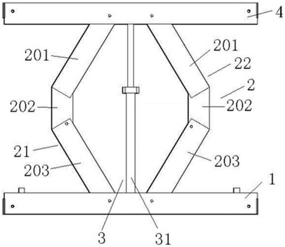
[0059] like figure 1 As shown, the basic structure of the universal support combination frame support unit includes a base plate 1, a top plate 4, a height adjustment device 2 and a support device 3; the height adjustment device 2 and the support device 3 are located between the base plate 1 and the top plate 4, and the One end of the height adjustment device 2 and the support device 3 is connected with the bottom plate 1, and the other end of the height adjustment device 2 and the support device 3 is connected with the top plate 4;

[0060] The bottom plate 1 and the top plate 4 are grooved plates vertically connected with baffles at both ends, each surface of the grooved plate is provided with a connection hole, and the two support units are realized through the cooperation of the connector and the connection hole. Connection; the two long side walls of the groove plate are provided with screw holes connecte...

Embodiment 1-1

[0065] The support device is a universal support combination frame support unit of threaded rod support type top:

[0066] like figure 1 As shown, the basic structure of the support unit of the universal support combination frame is as described above, and its supporting device is a threaded rod support type top 31, which is located in the middle of the height adjustment device 2;

[0067] like Figure 5 As shown, the threaded rod top includes a first round tube 311, a rotating handle 312 and a second round tube 313; one end of the first round tube 311 is provided with a threaded hole, and the other end is connected to the bottom plate 1; One end surface of two round pipes 313 is provided with a screw thread matched with the channel, and the other end is connected with the top plate 4; the rotating handle 312 is connected with the second round pipe 313, and the second round pipe 313 is adjusted into the first round pipe through the rotating handle 312 The length of the chann...

Embodiment 1-2

[0069] Universal support combination frame support unit with single threaded rotating rod 23:

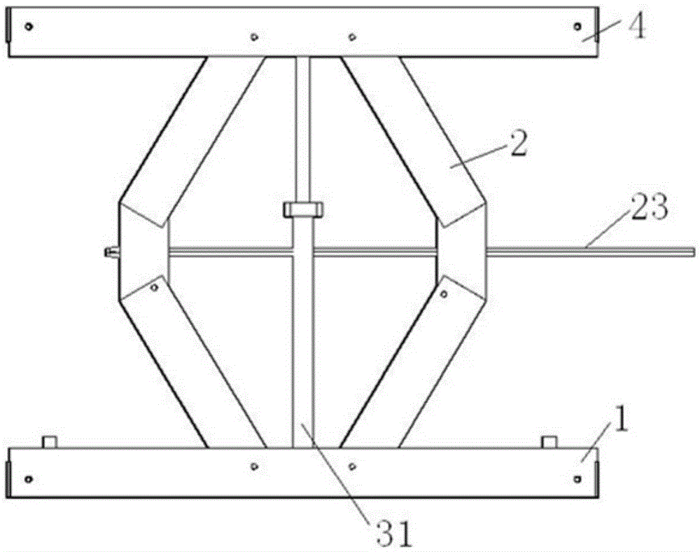
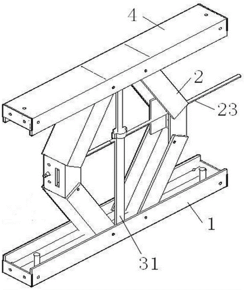
[0070] The basic structure of this embodiment is the same as that of Embodiment 1-1, and the difference from Embodiment 1-1 is that: the height adjustment device 2 of the universal support combination frame support unit can also include one Single threaded swivel rod 23 (see figure 2 , image 3 );

[0071] like Image 6 As shown, the single threaded rotating rod 23 is made up of a cylindrical long rod and a rod end 233 of an unequal cylinder; the cylindrical long rod is respectively provided with a threaded section 231 and a non-threaded section 232; One end of the threaded section 232 is connected to the threaded section 231 , and the other end is connected to the rod end 233 ; the single threaded rotating rod 23 passes through the second connecting plate of the two movable connecting plates 21 , 22 in turn.

[0072] As a transformation of Embodiment 1-2 of the present invent...


PUM


Abstract

A universal supporting combined frame supporting unit comprises a bottom plate, a top plate and a height adjusting device.The height adjusting device comprises two same movable connecting plates symmetrically arranged, wherein each movable connecting plate comprises a first connecting plate, a second connecting plate and a third connecting plate which are movably connected in sequence.The height adjusting device is located between the bottom plate and the top plate, one end of each first connecting plate is connected with the bottom plate, and one end of each third connecting plate is connected with the top plate.A universal supporting combined frame comprises a supporting device located in the middle of the height adjusting device or on the two sides of the height adjusting device.The bottom plate is further provided with columns and rolling wheels, wherein the columns are partially hollow, and the rolling wheels are embedded in the hollow parts of the columns.The universal supporting combined frame composed of a plurality of supporting units connected through connecting pieces is simple in structure, small in occupied area, firm, high in frame erecting efficiency and repeated utilization rate, capable of saving energy, environmentally friendly, low in preparing cost and capable of meeting various building construction requirements.

Description

technical field [0001] The invention relates to a building construction support frame and components thereof, in particular to a support unit of a universal support combined frame and a universal support combined frame. Background technique [0002] Traditional support systems and operating platforms usually use fasteners to connect rods, which is complicated to operate. Due to the quality of fasteners and unforeseen factors, local rods often slip or even collapse, making it difficult to guarantee safety and stability. . At the same time, the existing support frame is dangerous to be demolished, and it is inconvenient to assemble and use. Its components are too long, inconvenient to transport, slow to assemble, and its low frame erection efficiency takes up a lot of construction time on the construction site and delays the construction progress. In addition, the commonly used support frames for building high-rise buildings and bridges still have the following disadvantages:...

Claims


Application Information

Patent Timeline
Patent Type & Authority Applications(China)
IPC IPC(8): E04G1/18
CPCE04G1/18
Inventor 覃杨荣冯锦华梁雄韦继赫彭媛
Owner 广西建工第五建筑工程集团有限公司
Why Eureka
Try Eureka