Self-adaptive hydraulic potential energy converting device

A conversion device and self-adaptive technology, which is applied in the direction of engine components, machines/engines, mechanical equipment, etc., can solve the problems of turbine blade damage, hydraulic motor service life damage, etc., meet the requirements of low terrain conditions, reduce construction costs, The effect of increasing the range of use

Active Publication Date: 2016-06-01
NORTH CHINA ELECTRIC POWER UNIV (BAODING)
View PDF5 Cites 15 Cited by
  • Summary
  • Abstract
  • Description
  • Claims
  • Application Information

AI Technical Summary

Problems solved by technology

[0005] In view of this, the purpose of the present invention is to overcome the pressure of the compressed air in the prior art that will change drastically with the rapid change of the gas volume, which will cause greater damage to the service life of mechanical equipment such as hydraulic motors, and the constantly changing water head. For problems such as large damage to the blades of the water turbine, an adaptive hydraulic potential energy conversion device is proposed. The two ends of the adaptive hydraulic potential energy conversion device can be connected to high-low pressure potential energy sources with different potential energy. It is determined that each hydraulic cylinder is connected to a potential energy source of a certain potential energy, thereby generating different pressure differences and obtaining resultant forces of different directions and sizes, thereby determining the movement direction and speed of the hydraulic transmission mechanism, and making the movement of the hydraulic transmission mechanism The process realizes adaptive change

Method used


Image

  • Self-adaptive hydraulic potential energy converting device
  • Self-adaptive hydraulic potential energy converting device
  • Self-adaptive hydraulic potential energy converting device

Examples


Embodiment Construction

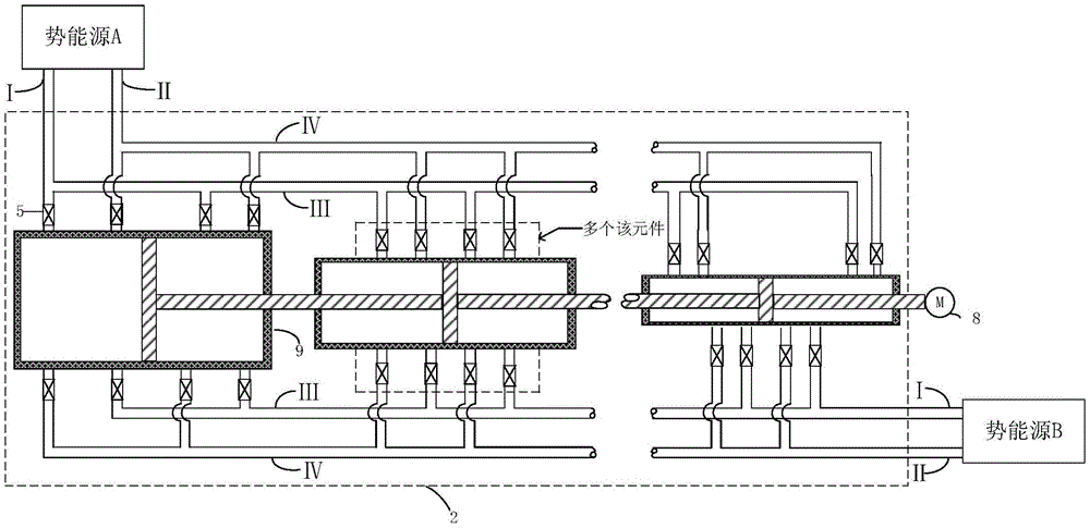
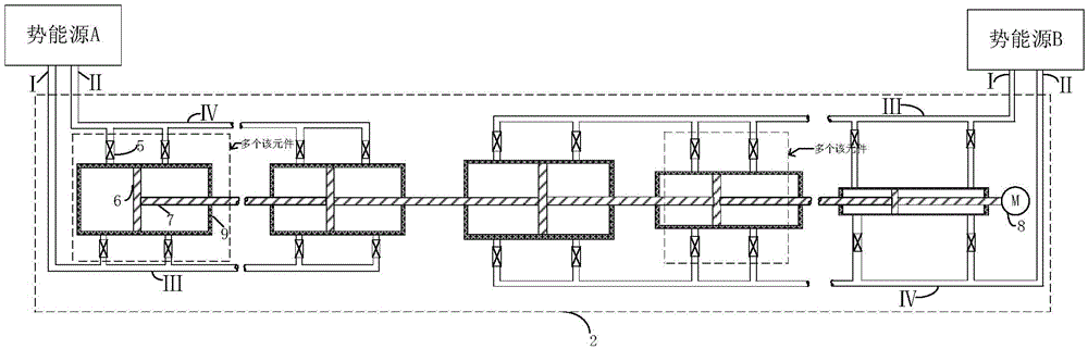
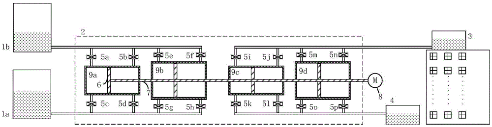
[0034] The present invention will be described in detail below in conjunction with the accompanying drawings.

[0035] Detailed exemplary embodiments are disclosed below. However, specific structural and functional details disclosed herein are merely for purposes of describing example embodiments.

[0036] It should be understood, however, that the invention is not limited to the particular exemplary embodiments disclosed, but covers all modifications, equivalents, and alternatives falling within the scope of the disclosure. Throughout the description of the figures, the same reference numerals denote the same elements.

[0037] Also, it should be understood that as used herein, the term "and / or" includes any and all combinations of one or more of the associated listed items. Also it will be understood that when a component or unit is referred to as being “connected” or “coupled” to another component or unit, it can be directly connected or coupled to the other component or ...


PUM


Abstract

Provided is a self-adaptive hydraulic potential energy converting device. The device comprises a first hydraulic cylinder set, a second hydraulic cylinder set, a first potential energy source, a second potential energy source, multiple valves connected with the corresponding hydraulic cylinders, pistons in the hydraulic cylinders and piston rods connected with the pistons, wherein the first hydraulic cylinder set and the second hydraulic cylinder set are each composed of multiple hydraulic cylinders of different sectional areas. The first hydraulic cylinder set is connected to the first potential energy source through the corresponding valves, and the second hydraulic cylinder set is connected to the second potential energy source through the corresponding valves. The piston rods of the first hydraulic cylinder set and the pistons of the second hydraulic cylinder set are connected in series. The first potential energy source is used for pushing the first hydraulic cylinder set and the second hydraulic cylinder set by reducing potential energy, the second potential energy source increases the potential energy through movement of the first hydraulic cylinder set and the second hydraulic cylinder set, and the area ratio of the first hydraulic cylinder set to the second hydraulic cylinder set is adjusted through the multiple valves on the basis of the potential energy changes of the first potential energy source and the second potential energy source. Energy conversion and transmission of two or more sets of different potential energies can be achieved through the self-adaptive hydraulic potential energy converting device.

Description

technical field [0001] The invention relates to the technical field of mechanical transmission devices, in particular to the technology of hydraulic power assist potential energy conversion devices. Background technique [0002] In recent years, with the rapid development of new energy sources, compressed air energy storage and power generation technologies have also been continuously improved. There are many technologies that use compressed air expansion to promote water power generation in many existing technologies. However, in this technology of using compressed air with water alone to generate electricity, the pressure of compressed air will change drastically with the rapid change of gas volume, which will cause great damage to the service life of mechanical equipment such as hydraulic motors. [0003] With the continuous development of pumped storage power generation technology, the design of traditional water turbines still limits the highest efficiency of water turb...

Claims


Application Information

Patent Timeline
Patent Type & Authority Applications(China)
IPC IPC(8): F03B13/00
CPCF03B13/00
Inventor 姜彤郑祥常马娴陈伟丽傅昊何旭洁
Owner NORTH CHINA ELECTRIC POWER UNIV (BAODING)
Why Eureka
Try Eureka