
Pacemaker system analyzer and battery box thereof

A battery box and battery technology, which is applied to battery components, circuits, electrical components, etc., can solve the problems that the power cannot be cut off immediately, and the battery box is difficult to open and open.

Active Publication Date: 2016-06-01
MICROPORT SORIN CRMSHANGHAICO LTD
View PDF3 Cites 6 Cited by
  • Summary
  • Abstract
  • Description
  • Claims
  • Application Information

AI Technical Summary

Problems solved by technology

[0004] The purpose of the present invention is to provide a pacing system analyzer and its battery box, to solve the problem that the existing battery box is difficult to open and cannot be powered off at the same time

Method used


Image

  • Pacemaker system analyzer and battery box thereof
  • Pacemaker system analyzer and battery box thereof
  • Pacemaker system analyzer and battery box thereof

Examples


Embodiment 1

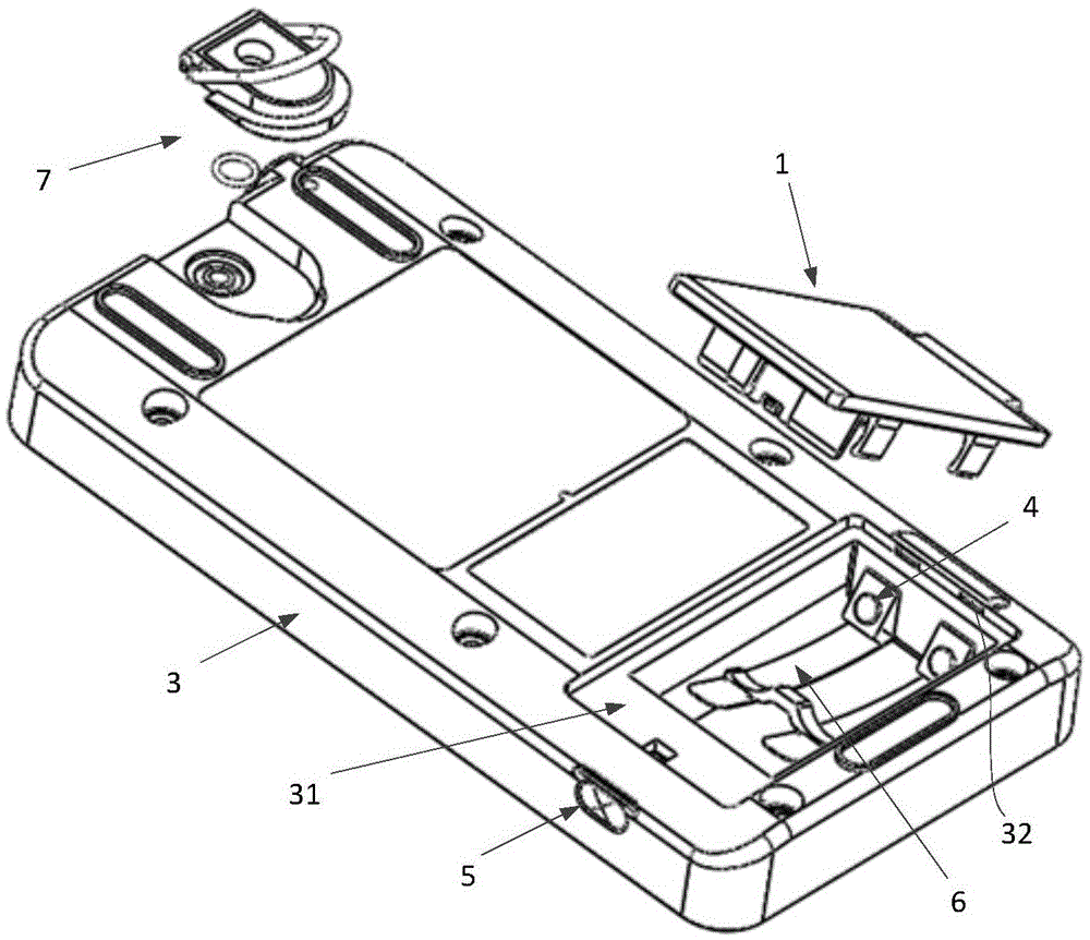
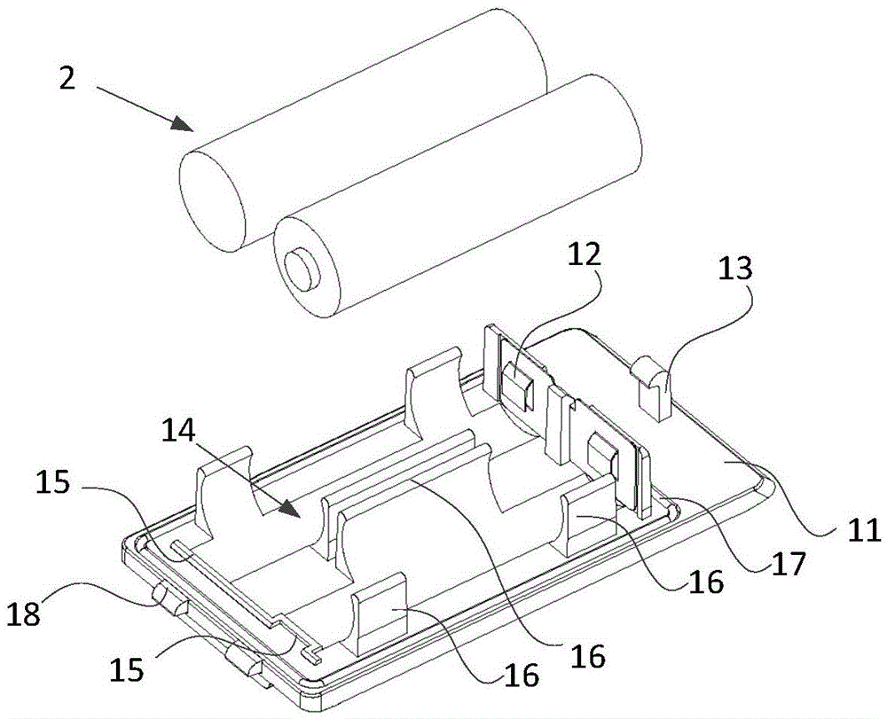
[0037] Such as Figure 1-7 As shown, this embodiment provides a battery box, including:

[0038] The battery module 1 is used to fix the battery 2, and includes a housing 11, a first electrode reed 12 and a buckle end 13, and the first electrode spring 12 and the buckle end 13 are respectively fixed on the housing 11 ;

[0039] The box body 3 has a battery compartment 31 for matching with the battery module. The battery compartment 31 is provided with a second electrode reed 4 fixed on the box body 3. The two poles of the battery 2 can be connected with the battery module respectively. The first electrode reed 12 is connected to the second electrode reed 4;

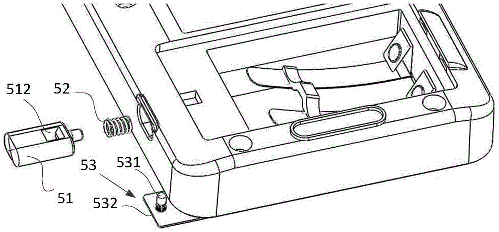
[0040] The locking module is used for fixing (also referred to as locking) the battery module 1 on the box body 3, and includes a locking buckle 51, a locking buckle spring 52 and a limiter for limiting the position of the locking buckle 51. Positioning device 53, through the lock 51, the lock spring 52 is inserted int...

Embodiment 2

[0057] Different from the first embodiment, another structure of the pop-up module 6 is provided in the second embodiment. Please refer to Figure 8-9 , the ejection module 6 includes a pin 61, a pin spring 62 and a pressing cap 63, the pin spring 62 is arranged in the mounting hole of the box body 3, and the pressing cap 63 is fixed in the mounting hole for Limiting the pin 61, the first end of the pin 61 is located between the pin spring 62 and the pressing cap 63, and the second end of the pin 61 exposes the pressing cap 63 and the mounting hole, The battery module 1 can press down the second end of the pin 61 into the pressing cap 63 and fix it on the box body 3 , the second end can be in contact with the battery module 1 when locked, and the lock When tight, the pin spring 62 is in a compressed state.

[0058] If it is necessary to unlock the battery module 1, the pin 61 rebounds quickly to eject the battery module 1, which facilitates the removal of the battery module ...


PUM


Abstract

The invention provides a battery box which comprises a battery module, a box body with a battery cabin, a locking module and a pop-up module, wherein the battery module is used for fixing a battery and comprises a shell, a first electrode reed and a buckling end; a second electrode reed fixed on the box body is arranged in the battery cabin, and two poles of a battery are respectively connected with the first electrode reed and the second electrode reed; the locking module comprises a lock catch, a lock catch spring and a limiting device for limiting the lock catch, the lock catch spring is inserted into the box body through the lock catch, and the buckling end is buckled in the box body through the lock catch; the pop-up module is used for the popping out the buckling end. The invention provides a pacemaker system analyzer and the battery box thereof; the process of the opening the battery box is simple, the battery is conveniently taken down, and the battery module can be popped out while the battery box is opened, so that the battery can be quickly separated from the second electrode reed, and further, quick power-off is realized.

Description

technical field [0001] The invention relates to an electronic device, in particular to a pacing system analyzer and its battery box. Background technique [0002] Electronic devices need power supply for normal use, and battery power supply is a common power supply method. In order to fix the battery and protect the battery from the interference of the external environment, it is necessary to place the battery in the battery box. In daily use, it is often necessary to replace the battery in the battery box, and to take out the battery, the battery box needs to be opened. [0003] In the prior art, in order to open the battery box, the battery box needs to be opened manually. However, the solution of manually opening the battery box often requires multiple operations to successfully open the battery box, which is time-consuming, labor-intensive, and inefficient. In addition, for small electronic medical devices such as pacing system analyzers, if the power cannot be cut of...

Claims


Application Information

Patent Timeline
Patent Type & Authority Applications(China)
IPC IPC(8): H01M2/10H01M2/20H01M2/34H01M50/20H01M50/247H01M50/298H01M50/572
CPCH01M50/213H01M50/502H01M50/597H01M50/572Y02E60/10
Inventor 何明晨
Owner MICROPORT SORIN CRMSHANGHAICO LTD
Learn More