
Antenna reflector and antenna

A reflector and antenna technology, applied to antennas, electrical components, etc., can solve the problems of wasting materials, increasing processing costs, increasing costs, etc., and achieves the effect of improving front-to-back ratio indicators, reducing occupied space, and reducing material waste.

Active Publication Date: 2019-09-17
COMBA TELECOM TECH (GUANGZHOU) CO LTD
View PDF2 Cites 0 Cited by
  • Summary
  • Abstract
  • Description
  • Claims
  • Application Information

AI Technical Summary

Problems solved by technology

[0004] However, the above-mentioned methods have some disadvantages: the first method will increase the cost, and the beam width of the antenna will be narrowed; the second method is expensive and wastes materials; the third method not only increases the processing cost, but also the structure is too complex

Method used


Image

  • Antenna reflector and antenna
  • Antenna reflector and antenna
  • Antenna reflector and antenna

Examples


Embodiment 1

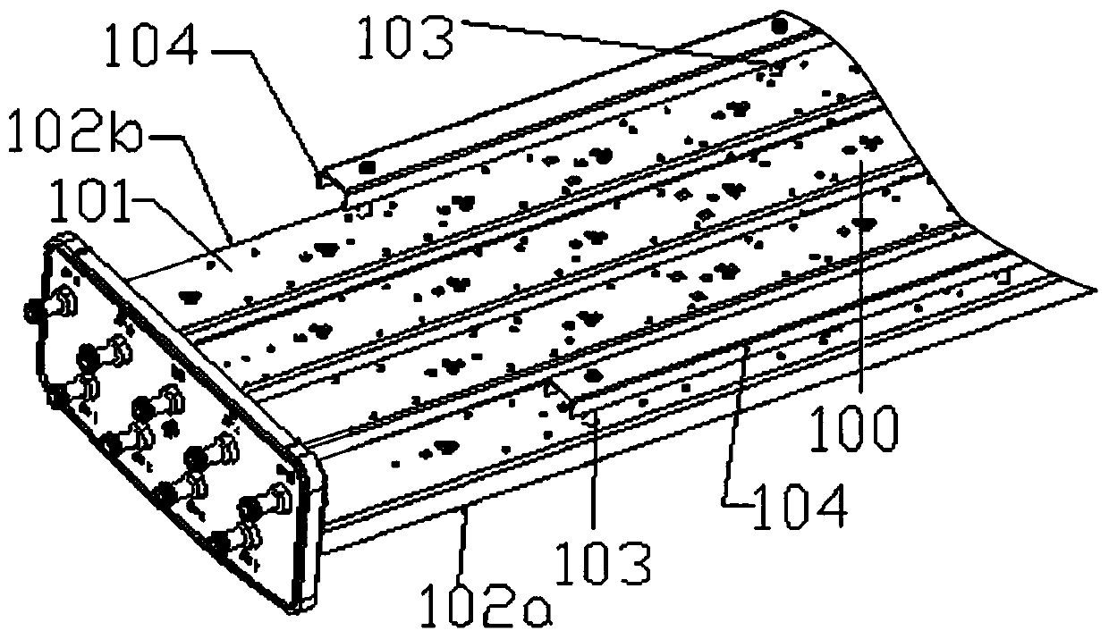
[0033] see figure 2 , which is a schematic diagram of the first embodiment of the antenna reflector based on the present invention.

[0034] In this embodiment, the reflecting plate 100 also includes a bottom plate 101 , two side plates 102 a , 102 b , several insulating support columns 103 , and two choke slots 104 .

[0035] Two choke slots 104 are symmetrically arranged on both sides of the lower side of the bottom plate, and each choke slot 104 is vertically arranged on the corresponding insulating support post 103 by the first loading section 104a located outside the corresponding insulating support post 103 103 at the bottom of the second loading section 104b and the third loading section 104c located inside the corresponding insulating support column 103 .

[0036] Specifically, the first loading section 104a and the third loading section 104c are symmetrically and vertically arranged on the left and right sides of the second loading section 104b. And the outer edges...

Embodiment 2

[0040] see image 3 , which is a schematic diagram of the second embodiment of the antenna reflector based on the present invention.

[0041] This embodiment is derived from the first embodiment, and its difference from the first embodiment is that the outer edge of the first loading section 104a of the choke groove 104 is longitudinally staggered from the outer edges of the side plates 102a, 102b, and the The outer edge of the first loading section 104a exceeds the outer edges of the side plates 102a, 102b, and the horizontal distance between them does not exceed 0.2 times of the working wavelength.

Embodiment 3

[0043] see Figure 4 , which is a schematic diagram of the third embodiment of the antenna reflector based on the present invention.

[0044] This embodiment is derived from the first embodiment, and its difference from the first embodiment is that the outer edge of the first loading section 104a of the choke groove 104 is longitudinally staggered from the outer edges of the side plates 102a, 102b, and the The outer edges of the side plates 102a, 102b exceed the outer edge of the first loading section 104a, and the horizontal distance between them is no more than 0.2 times the working wavelength.


PUM


Abstract

The invention provides an antenna reflective plate (100). The antenna reflective plate (100) comprises a bottom plate (101), a pair of side plates (102a, 102b), choke grooves (104) and an insulating supporting column (103), wherein the pair of side plates (102a, 102b) are arranged on the two sides of the bottom plate (101) and extend upwards; the choke grooves (104) are formed in the two sides of the cross section of the bottom plate (101) and positioned on the lower side of the bottom plate (101), and the openings of the choke grooves face to the bottom plate (101); the insulating supporting column (103) is arranged between the choke grooves (104) and the bottom plate (101) and used for keeping the insulation between the choke grooves (104) and the bottom plate (101). Compared with the prior art, the antenna reflective plate (100) provided by the invention is relatively small in size, so that waste of materials is lowered and the occupied space is decreased; the choke grooves (104) that are insulated from the bottom plate (101) are loaded on the lower side of the bottom plate (101) of the reflective plate (100), so that the backward radiation of the antenna is effectively restrained, and the front-to-back ratio index is improved; and in addition, the antenna reflective plate is simple in structure and easy to machine.

Description

technical field [0001] The invention relates to the technical field of antennas in mobile communications. Specifically, the present invention relates to an antenna reflector and an antenna using the antenna reflector. Background technique [0002] With the development of mobile communication, the communication capacity of the system is continuously increasing, and the distance between cells is getting smaller and smaller. In order to reduce the mutual interference between cells, an effective method is to increase the front-to-back ratio of the base station antenna. [0003] At present, there are three commonly used methods to improve the front-to-back ratio of the antenna: the first is to widen the reflector of the antenna; the second is to add a cover plate behind the antenna bottom plate; the third is to add more to the side of the antenna reflector. Secondary bends or slotted slots. [0004] However, the above-mentioned methods have some disadvantages: the first method ...

Claims


Application Information

Patent Timeline
Patent Type & Authority Patents(China)
IPC IPC(8): H01Q19/10H01Q15/14
Inventor 周峰李明超卢吉水黄立文李轶帆
Owner COMBA TELECOM TECH (GUANGZHOU) CO LTD
Learn More