Electronic linear accelerator

A linear accelerator and electronic technology, applied in the field of medical equipment, can solve the problems of inability to accurately locate the irradiation position of treatment rays, decrease in the clarity of imaging images, and inability to complete precise treatment, etc., and achieve good promotion, low cost, and easy operation.

Active Publication Date: 2016-06-01
SHANGHAI UNITED IMAGING HEALTHCARE
View PDF9 Cites 11 Cited by
  • Summary
  • Abstract
  • Description
  • Claims
  • Application Information

AI Technical Summary

Problems solved by technology

[0006] The problem solved by the present invention is that the loss of the electron beam after the KV-class electron beam of the existing homologous double-beam electron linear accelerator passes through the deflection magnet

Method used


Image

  • Electronic linear accelerator
  • Electronic linear accelerator
  • Electronic linear accelerator

Examples


Embodiment Construction

[0030] In order to make the above objects, features and advantages of the present invention more comprehensible, specific embodiments of the present invention will be described in detail below in conjunction with the accompanying drawings.

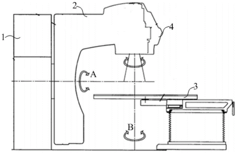
[0031] refer to figure 1 , the homologous double-beam IGRT medical electron linear accelerator of the present embodiment comprises:

[0032] Fixed frame 1; rotating frame 2 located on one side of fixed frame 1; treatment bed 3, on which the patient receives treatment; irradiation head 4 connected to the top of rotating frame 2, opposite to treatment bed 3 , the imaging rays and therapeutic rays emitted from the irradiation head 4 can be irradiated on the patient. The rotating frame 2 can rotate back and forth around the central axis of the fixed frame 1 along the direction A, and the treatment couch 3 can also rotate around the axis of the base along the direction B to adjust the position of the irradiation head 4 relative to the human bo...


PUM

PropertyMeasurementUnit
Densityaaaaaaaaaa

Abstract

The invention provides an electronic linear accelerator, which comprises an electron beam emitting device used for emitting a kV-level electron beam or an mV-level electron beam, a magnetic deflection system, a therapeutic target and an imaging target. The mV-level electron beam can enter the magnetic deflection system and then shoots out of the magnetic deflection system after being deflected in the magnetic deflection system. The therapeutic target is used for receiving the mV-level electron beam shot out of the magnetic deflection system. The mV-level electron beam bombards the therapeutic target to generate therapeutic rays. The imaging target is positioned between the electron beam emitting device and the magnetic deflection system and is used for receiving the kV-level electron beam. The kV-level electron beam bombards the imaging target to generate imaging rays. According to the technical scheme of the electronic linear accelerator, the design limitation of an existing homologous double-beam linear accelerator due to the existence of a deflection magnet is broken through. The kV-level electron beam will not enter the magnetic deflection system to be deflected, while the kV-level electron beam directly bombards the imaging target to generate imaging rays. The energy of the imaging rays can meet the imaging requirement, so that the utilization efficiency of the kV-level electron beam is improved. Therefore, formed images are high in quality. Meanwhile, the irradiation part can be accurately positioned and the setup error is lowered.

Description

technical field [0001] The invention relates to the field of medical equipment, in particular to an electron linear accelerator. Background technique [0002] With the development of precise radiation therapy technology, image-guided radiation therapy (ImageGuideRadiationTherapy, IGRT) technology is gradually being clinically applied. Using IGRT technology, on the one hand, before the patient receives treatment, imaging can be used to verify the irradiation position of the patient. After the irradiation position is confirmed, the therapeutic irradiation can be performed to reduce the positioning error. On the other hand, during the treatment process, the changes of the tumor can be tracked in real time, and the treatment conditions can be adjusted according to the change of the tumor position so that the irradiation field closely "follows" the target area to achieve precise treatment. [0003] Since the radiation used for treatment is usually MV-level energy X-rays, but MV-...

Claims


Application Information

Patent Timeline
IPC IPC(8): H05H9/00A61N5/10
Inventor 刘艳芳章健汪鹏李贵宋瑞英潘刚倪成
Owner SHANGHAI UNITED IMAGING HEALTHCARE
Why Eureka
Try Eureka