Fuel high pressure pump with outlet valve

A high-pressure pump and outlet valve technology, which is applied to fuel injection pumps, fuel injection devices, special fuel injection devices, etc., to achieve the effect of low cost and noise avoidance

Active Publication Date: 2018-09-28
ROBERT BOSCH GMBH
View PDF7 Cites 0 Cited by
  • Summary
  • Abstract
  • Description
  • Claims
  • Application Information

AI Technical Summary

Problems solved by technology

[0003] The problem on which the invention is based is solved by the following high-pressure fuel pump

Method used


Image

  • Fuel high pressure pump with outlet valve
  • Fuel high pressure pump with outlet valve
  • Fuel high pressure pump with outlet valve

Examples


Embodiment Construction

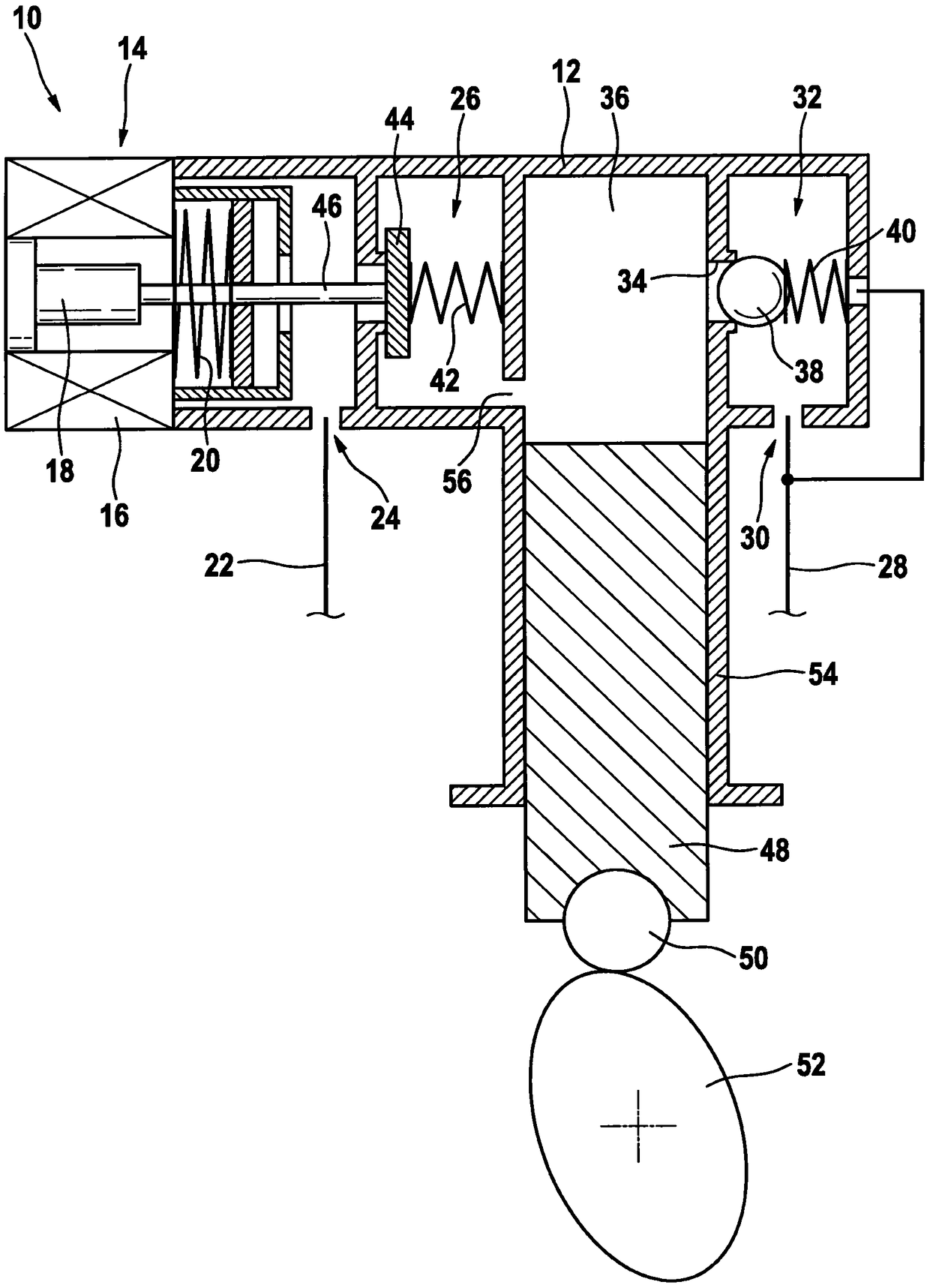
[0018] figure 1 A simplified schematic diagram of the high-pressure fuel pump 10 is shown in axial section. The high-pressure fuel pump 10 is a component of a fuel system (not shown) of an internal combustion engine (not shown) of a motor vehicle. The fuel high-pressure pump 10 has a housing 12, as shown in the left part of the figure, an electromagnet 14 is arranged in the housing 12, and the electromagnet 14 has a magnet coil 16, an armature 18, and an armature spring 20.

[0019] In addition, the high-pressure fuel pump 10 includes an inlet 24 and an outlet 30. The inlet 24 has an inlet valve 26 and the inlet 24 is connected to a low-pressure pipe 22, and the outlet 30 has an outlet valve 32 and the outlet 30 is connected to a high-pressure pipe. 28 connections. The high-pressure accumulator ("pressure accumulator") connected to the high-pressure pipe 28 is not shown here. In the open state, the outlet valve 32 is hydraulically connected to the supply chamber 36 through the ...


PUM


Abstract

A high-pressure fuel pump includes an outlet valve, a valve ball, a valve spring that acts on the valve ball in a closing direction, and a stop body for the valve ball. The stop body has a stop section that limits the opening stroke of the valve ball, and the valve spring is supported by the stop body. The stop body has a cut-out section that at least partially accommodates the valve spring and that has a radial inner periphery which forms a guide for the valve spring.

Description

Technical field [0001] The invention relates to a high-pressure fuel pump. Background technique [0002] High-pressure fuel pumps (especially piston pumps for internal combustion engine fuel systems) have been published on the market. This type of fuel high-pressure pump usually includes an inlet valve and an outlet valve, which can be opened and closed according to the control device and / or according to the fuel pressure. During the suction stroke, the outlet valve can close the fuel storage (pressure accumulation pipe) under pressure against the supply chamber of the fuel high-pressure pump. Conversely, if the fuel pressure in the supply chamber exceeds the sum of the reaction force caused by the pressure in the fuel storage and the closing spring force, the outlet valve can be opened. Summary of the invention [0003] The problem on which the present invention is based is solved by the following high-pressure fuel pump. The preferred embodiment provides advantageous improvem...

Claims


Application Information

Patent Timeline
Patent Type & Authority Patents(China)
IPC IPC(8): F02M59/46F02M63/00
CPCF02M59/462F02M63/0054F02M2200/50
Inventor G·泰克M·克莱德尔S·施特里茨尔
Owner ROBERT BOSCH GMBH
Why Eureka
Try Eureka