Fill level sensor

A technology of liquid level sensor and potentiometer, which is applied in the direction of float liquid level indicator, liquid level indicator, instrument, etc., can solve the problem of high cost and achieve the effect of low cost and low corrosion resistance

Inactive Publication Date: 2016-06-01
CONTINENTAL AUTOMOTIVE GMBH
View PDF5 Cites 2 Cited by
  • Summary
  • Abstract
  • Description
  • Claims
  • Application Information

AI Technical Summary

Problems solved by technology

But the cost of this material is very high

Method used


Image

  • Fill level sensor
  • Fill level sensor
  • Fill level sensor

Examples


Embodiment Construction

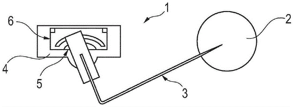
[0021] figure 1 A level sensor 1 with a lever arm 3 holding a float 2 is shown. This liquid level sensor 1 is used in a fuel tank not shown. The lever arm 3 is mounted pivotably on the carrier 4 and pivots depending on the fill level of the fuel arranged in the fuel tank. The swing of the lever arm 3 is detected by a potentiometer 5 . The potentiometer 5 has a carrier element 6 arranged on a carrier 4 .

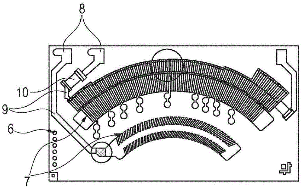
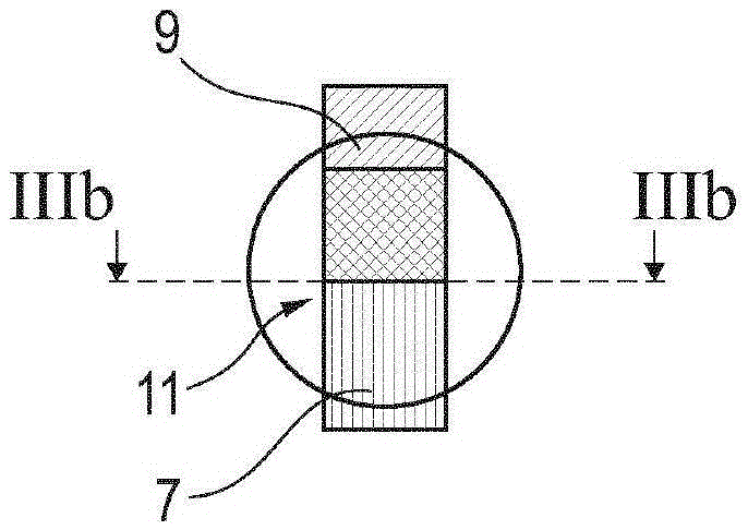
[0022] The carrier element 6 of the potentiometer 5 is in figure 2 Enlarged display. Arranged on the carrier element 6 are function-dependent structures, such as slide rail structures 7 and electrical connection areas 8 . Furthermore, the carrier element 6 also has inactive structures, such as conductor structures 9 of the lead-in lines, carrier conductors in the resistive region and switching conductors. The resistor structure 10 forms an ohmic resistor in the conductor structure 9 . A contact bridge, not shown, arranged on the lever arm 3 slides on the slide rail st...


PUM


Abstract

A fill level sensor (1) for a fuel tank of a motor vehicle comprises electrical structures that consist of different materials. Sliding contact track structures (7) which are exposed to the fuel consist of a gold-containing paste. Conductor structures (9) are protected by a cover (12, 14) from contact with the fuel and consist of an especially inexpensive material. The fill level sensor (1) therefore is highly resistant to corrosive fuels and can be produced at low cost.

Description

technical field [0001] The invention relates to a fill level sensor for a fuel tank of a motor vehicle, which has a carrier element, a potentiometer for detecting the fill level, a slide rail structure of the potentiometer arranged on the carrier element and a on the conductor structure. Background technique [0002] Fill level sensors of this type are frequently used in the fuel tanks of current motor vehicles and are known from practice. Due to the arrangement in the fuel tank, the structures arranged on the carrier element are exposed to the fuel. Alcoholic fuels, however, are generally very corrosive. For the structure mounted on the carrier element in the known fill level sensors, therefore, particularly corrosion-resistant and gold-containing materials are used for such structures. But the cost of this material is very high. Inexpensive silver-containing materials used for such structures lead to rapid corrosion of structures exposed to fuel. Contents of the inve...

Claims


Application Information

Patent Timeline
Patent Type & Authority Applications(China)
IPC IPC(8): G01F23/36
CPCG01F23/363G01F23/36
Inventor E·马特曼G·卡尔魏特R·彼得
Owner CONTINENTAL AUTOMOTIVE GMBH
Why Eureka
Try Eureka