Using method of double-tape single-layer anti-unfastening zipper through insertion
An anti-insertion, single-layer technology, applied in the direction of application, sliding fastener components, fasteners, etc., can solve the problem of insufficient zipper strength and achieve the effect of increasing difficulty
- Summary
- Abstract
- Description
- Claims
- Application Information
AI Technical Summary
Problems solved by technology
Method used
Image

Examples
Embodiment Construction
[0011] Below in conjunction with accompanying drawing, the present invention is further described:
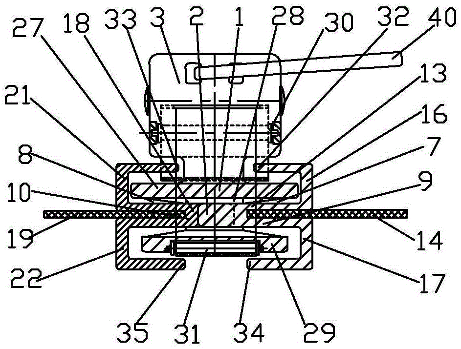
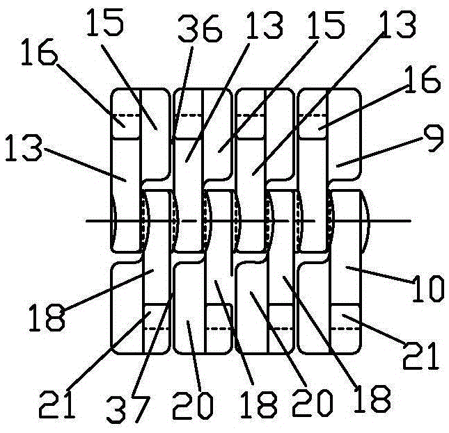
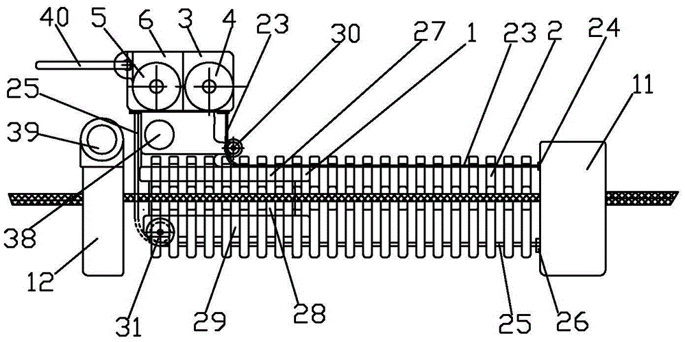
[0012] figure 1 Schematic diagram of the structure of the double-volume single-layer anti-insertion zipper shown, figure 2 The partial schematic diagram of the left anti-insertion piece and the right anti-insertion piece shown, image 3 shown figure 1 right view of and Figure 4 shown image 3 The top view of the double-roll single-layer anti-insertion zipper includes a chain base 1, a chain 2 and a steel tape measure 3, and the steel tape measure 3 includes an upper steel tape measure 4 and a lower steel tape measure 5, and the shell of the chain base 1, chain 2 and steel tape measure 3 6 connection; chain seat 1 is provided with left chain groove 7 and right chain groove 8, and chain 2 includes left chain 9, right chain 10, chain head sealing piece 11 and chain tail sealing piece 12, left chain 9 and right chain 10 and The chain head sealing piece 11 and the chain tail ...
PUM
 Abstract
Description
Claims
Application Information
PatSnap Eureka turns technology decisions into work you can execute. Powered by our Innovation Knowledge Graph, it runs expert workflows across engineering, life sciences, materials and intellectual property. Get your review-ready output in minutes.


