flat mop cleaning bucket flat mop

A technology for a flat mop and a cleaning bucket is applied to the field of mop cleaning buckets, which can solve the problems of high labor intensity, inability to operate continuously, and large volume of the bucket body, and achieve flexible and light up and down movements, good dehydration effect, and good cleaning effect.

Inactive Publication Date: 2018-03-27
ZHEJIANG XINGHAO PLASTIC
View PDF1 Cites 3 Cited by
  • Summary
  • Abstract
  • Description
  • Claims
  • Application Information

AI Technical Summary

Problems solved by technology

However, the flat mop has the following problems in use: before use, the wet mop needs to be manually squeezed dry, and then the mop can be fixed on the top of the flat mop main board for use, and after use, the mop needs to be folded off the flat mop main board Manual cleaning and squeezing not only have low work efficiency and high labor intensity, but also dirty hands when cleaning and squeezing, which can no longer meet the cleaning and sanitation requirements of the majority of users.
Although this structure has fast cleaning speed, high efficiency and good effect, and does not need to be manually squeezed, it is hygienic and clean to use, but there are also the following problems: one is that cleaning and dehydration cannot be carried out alternately, and the water in the bucket needs to be drained when cleaning and dehydration are completed. Dehydration can only be carried out after part or all of it is discharged, and it cannot be operated continuously, which brings inconvenience to users; second, due to the long length of the main board of the flat drag, the volume of the barrel is also relatively large, which not only wastes water resources, but also causes inconvenience to packaging, transportation and storage. bring inconvenience
For this reason, many manufacturers and people of insight carry out research and development, but there is no relatively satisfactory product on the market so far.

Method used


Image

  • flat mop cleaning bucket flat mop
  • flat mop cleaning bucket flat mop
  • flat mop cleaning bucket flat mop

Examples


Embodiment Construction

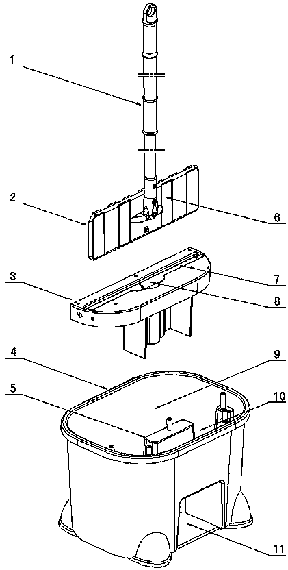
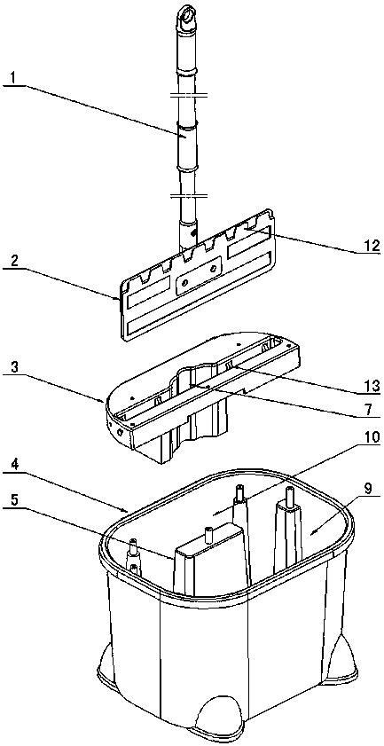
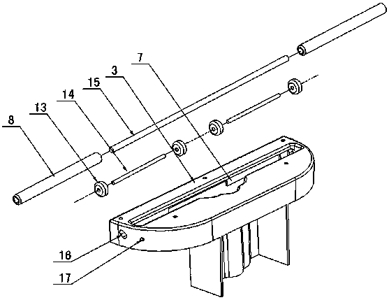
[0021] Figure 1 to Figure 5 As shown, the invention creates a specific embodiment of a flat mop cleaning barrel, which includes a barrel body 4 and a dehydration support seat 5, the barrel body 4 is provided with a cleaning area 9 and a dehydration area 10, and the dehydration support seat 5 is provided with On the barrel body 4 of the dehydration area 10, a dehydration support 3 is fixed on the dehydration support seat 5, and the dehydration notch 7 for the up and down movement of the flat drag main board 2 is provided on the dehydration support 3, corresponding to the mop side of the flat drag main board 2 The groove wall of the dehydration notch 7 is provided with a dehydration mechanism.

[0022] In order to facilitate dehydration, the dehydration mechanism includes a dehydration roller 8, a dehydration roller shaft 15, and at least one dehydration roller shaft 15 corresponding to the length of the mop is arranged on the mop side groove wall of the dehydration slot 7, and...


PUM


Abstract

The invention discloses a flat mop cleaning barrel. The flat mop cleaning barrel comprises a barrel body (4) and a dewatering support seat (5). The barrel body (4) is provided with a cleaning region (9) and a dewatering region (10). The dewatering support seat (5) is arranged in the dewatering region (10) of the barrel body (4). A dewatering support (3) is fixed to the dewatering support seat (5), a dewatering notch (7) is formed in the dewatering support (3), and a dewatering mechanism is arranged on one side wall of the dewatering notch (7). The dewatering mechanism comprises a dewatering roller (8) and a dewatering roller shaft (15). One side of the dewatering notch (7) is at least provided with one dewatering roller shaft (15). The dewatering roller shaft (15) is at least provided with a rotatable dewatering roller (8). The other side of the dewatering notch (7) is at least provided with a guide wheel shaft (14). The guide wheel shaft (14) is at least provided with a rotatable guide wheel (13). By the adoption of the structure, the advantages that the structure is simple and compact, operation and use are convenient, cleaning and dewatering can be conducted alternately, the size is small, storage is convenient, and the water saving effect is good are achieved.

Description

technical field [0001] The invention relates to a mop cleaning bucket, in particular to a flat mop cleaning bucket in which cleaning and dehydration can be performed alternately when the flat mop is in use. Background technique [0002] The mop rod of the traditional flat mop is fixed on the mop rod connector, the mop rod connector is hinged on the hinge seat, the hinge seat is hinged on the connector seat of the flat mop main board, and the mop is fixed on the flat mop by socketing, sticking or snapping. On the main board of the mop, the mop can always be kept in contact with the ground during use, and the mop can be easily removed when cleaning. Therefore, the flat mop is very popular among users. However, the flat mop has the following problems in use: before use, the wet mop needs to be manually squeezed dry, and then the mop can be fixed on the top of the flat mop main board for use, and after use, the mop needs to be folded off the flat mop main board Manual cleaning ...

Claims


Application Information

Patent Timeline
Patent Type & Authority Patents(China)
IPC IPC(8): A47L13/60
CPCA47L13/20A47L13/256A47L13/58A47L13/60
Inventor 贾兴行
Owner ZHEJIANG XINGHAO PLASTIC
Why Eureka
Try Eureka