Self-locking medical mouth gag

An opener and self-locking technology, which is applied in the field of medical devices, can solve the problems of patient pain, easy bending and deformation of the supporting part, inconvenient operation, etc., and achieve the effect of less pain for the patient, no psychological burden, and a wide range of applications

Inactive Publication Date: 2016-06-08
贝忠东
View PDF6 Cites 2 Cited by
  • Summary
  • Abstract
  • Description
  • Claims
  • Application Information

AI Technical Summary

Problems solved by technology

But this kind of spreader is bulky and inconvenient to operate. During the operation, the front end is located in the patient's oral cavity, and the rear end is located outside the oral cavity, which hinders the operation and causes more pain for the patient; The brace part is close to the inner wall of the patient's side of the cheek during use, which is inconvenient to operate; in addition, it is difficult to control the force of the lever operation, and the brace part is easy to bend and deform if there is a slight carelessness; in addition, the upper brace part and the lower brace part The included angle is fixed and cannot adapt to the individual differences of patients, which will affect the accuracy of distraction
In addition, in oral surgery such as dentistry, it is often necessary to passively open the patient's oral cavity mechanically to facilitate the operation. However, the existing oral retractors are generally large in size, and after the expansion, a large handle is left outside the patient's oral cavity. It causes psychological burden, and it is not convenient for further operation; lack of necessary locking mechanism, the opening mechanism is easy to loosen

Method used


Image

  • Self-locking medical mouth gag
  • Self-locking medical mouth gag
  • Self-locking medical mouth gag

Examples


Embodiment Construction

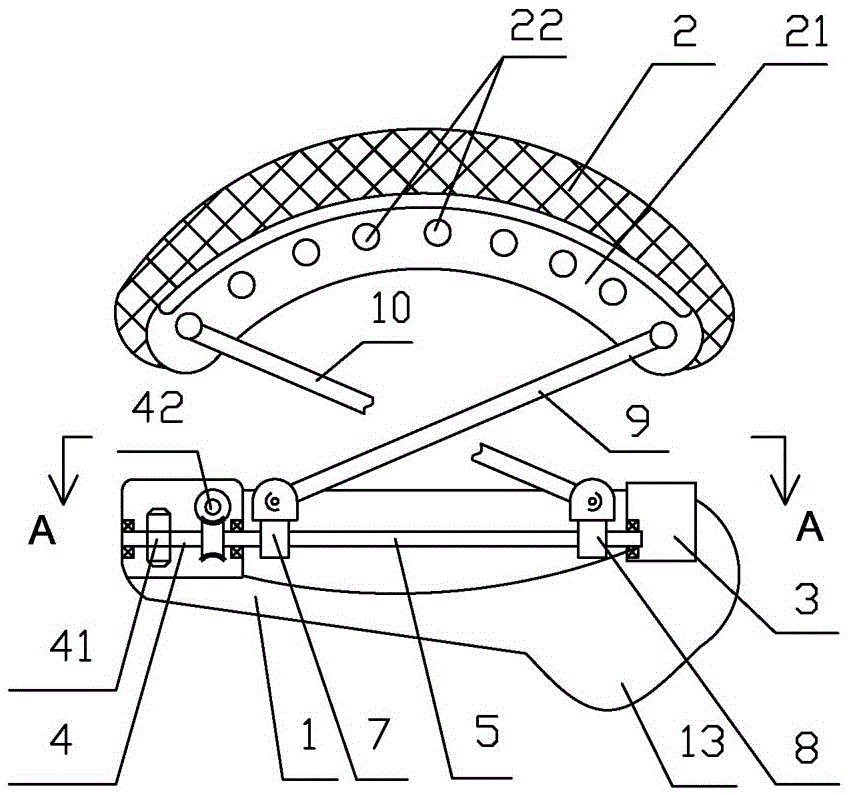
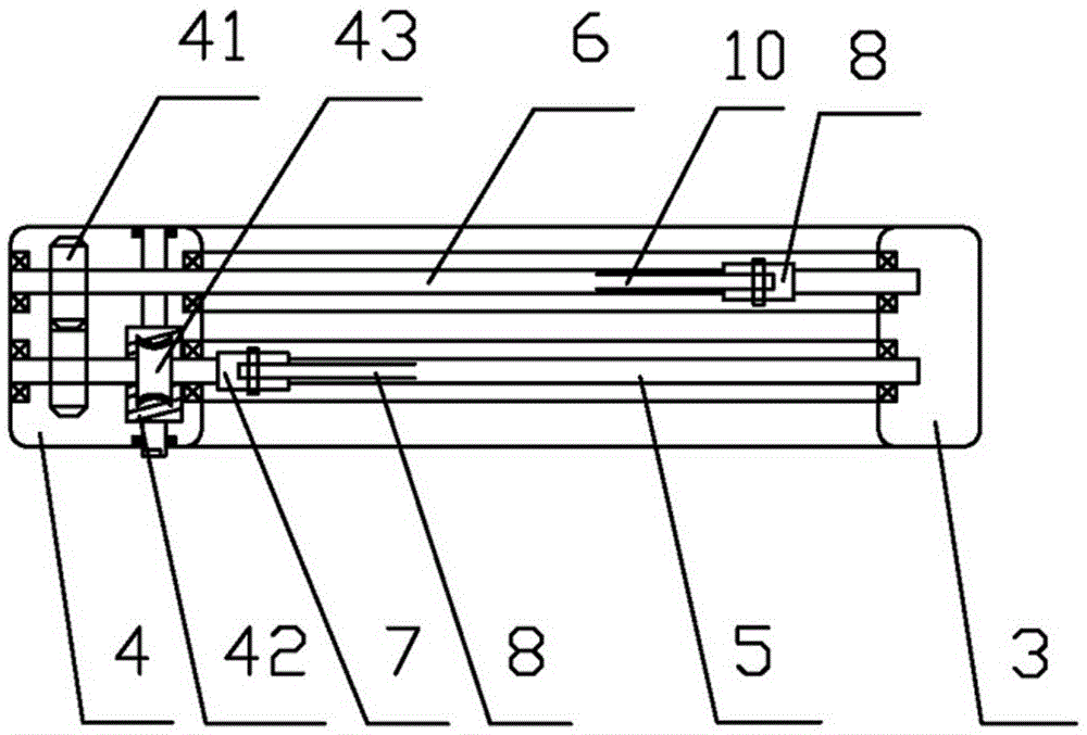
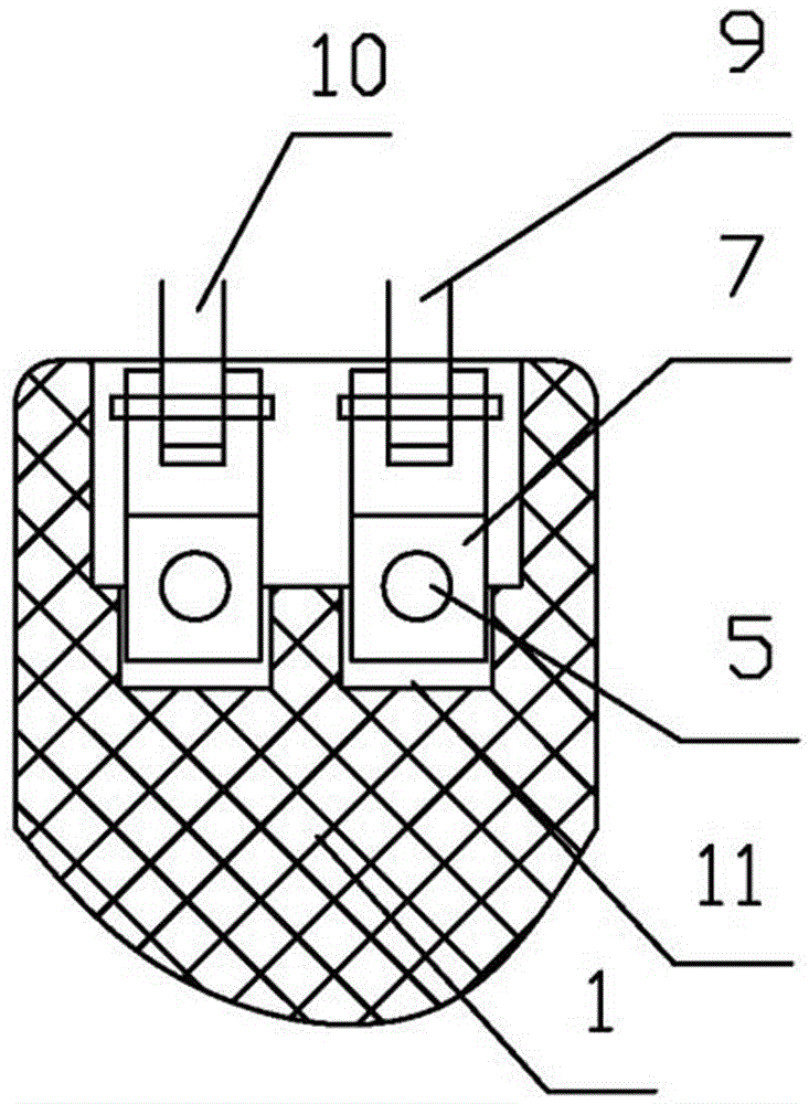
[0010] Such as figure 1 As shown, the self-locking medical gag described in the present invention includes a lower brace part 1 corresponding to the mandibular notch of the human body, an upper brace part 2 corresponding to the zygomatic arch corresponding to the maxillary notch of the human body, and an upper brace part 2 It is an upwardly convex arc shape with good elasticity. The lower supporting part 1 is in the shape of a concave arc, and a raised part 13 is provided under the front end of the lower supporting part 1. The raised part 13 can fit the groove part of the mandibular notch, which is helpful for firm positioning, precise. The upper surface of the lower supporting part 1 is provided with a slide bar groove 11, and the two ends of the slide bar groove 11 are respectively provided with a shaft seat 3 and a transmission box 4, and a bearing is installed between the shaft seat 3 and the transmission box 4. Sliding rods 5, 6; the middle sections of sliding rods 5, 6...


PUM


Abstract

The invention relates to medical equipment used for oral and maxillofacial surgical operation, in particular to a self-locking medical mouth gag. The self-locking medical mouth gag comprises a lower strutting part and an upper strutting part, wherein a shaft seat and a transmission case are arranged at the two ends of the lower strutting part respectively; sliding rods are mounted between the shaft seat and the transmission case through bearings; external threads are formed in the middle sections of the sliding rods between the shaft seat and the transmission case; each of the sliding rods is sleeved by a sliding block in a matched manner through the corresponding external thread; the sliding blocks are hinged to the lower ends of supporting rods; a strip-shaped groove is formed in the lower end of the upper strutting part; a plurality of shaft holes are formed in the groove; the upper ends of the supporting rods are mounted in the shaft holes through rotating shafts; a driving mechanism for driving the sliding rods to rotate is arranged in the transmission case. The mouth gag is simple in structure, convenient to use and reasonable in stress, ensures that a patient suffers from less pain, and can be adaptable to individual difference.

Description

technical field [0001] The invention relates to a medical instrument for stomatology and maxillofacial surgery, in particular to a self-locking medical mouth opener. Background technique [0002] There are two protrusions at the end of the mandibular branch of the mandible. The one located at the rear is called the condyle, which consists of the enlarged mandibular head at the upper end and the mandibular neck below the head. The mandibular condyle is elliptical, with a long inner and outer diameter and a short anteroposterior diameter. In lateral view, a transverse crest divides the top of the condyle into two oblique planes. The anterior slope is small, which is the functional surface, and is the load-bearing area of ​​the joint; the mandibular condyle is a prone area for jaw fractures, which can be caused by direct impact on the condyle, or can be caused by trauma to the chin or body of the mandible. Indirect fractures caused by blows are easily missed clinically. The ...

Claims


Application Information

Patent Timeline
Patent Type & Authority Applications(China)
IPC IPC(8): A61B1/24A61C19/00
CPCA61B1/24A61C19/00
Inventor 曹兰
Owner 贝忠东
Why Eureka
Try Eureka