
Paint spraying operation isolation structure

A technology for isolating structures and operations, applied in spray booths, spraying devices, coatings, etc., can solve the health hazards of operators, affect the health of operators and other problems, reduce the health hazards of operators, facilitate adjustments, and facilitate spray guns The effect of the angle

Inactive Publication Date: 2016-06-08
CHENGDU LIXIN SCI & TECH
View PDF3 Cites 7 Cited by
  • Summary
  • Abstract
  • Description
  • Claims
  • Application Information

AI Technical Summary

Problems solved by technology

[0003] The purpose of the present invention is to provide an isolation structure for spraying work, which solves the problem in the prior art that when spraying furniture, the operator is directly in contact with the high-concentration mist paint, which affects the health of the operator, and realizes reducing the impact on the operator during the spraying operation. Purpose of physical health hazard
Aiming at the problem that the existing painting operation is harmful to the health of operators, the present invention proposes a painting operation isolation structure

Method used


Image

  • Paint spraying operation isolation structure
  • Paint spraying operation isolation structure

Examples


Embodiment 1

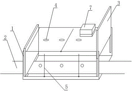
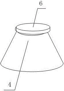
[0019] Such as figure 1 and figure 2 The shown isolation structure for painting operation includes a box body 1, and also includes a conveyor belt 2 passing through the inside of the box body 1 along the long axis direction of the box body 1, and the two sides of the long axis direction of the box body 1 are provided with There is a switchable box door 3, each surface of the box body 1 is provided with a number of spray gun jacks 4, the aperture of the spray gun jacks 4 increases linearly from the outside to the inside, and the box body 1 is made of transparent material As a result, the casing of the box 1 is also provided with a ventilation device 7 with an air inlet facing the inside of the box 1; the openings of the spray gun sockets 4 are hinged with isolation plates 6 . In this embodiment, the conveyor belt 2 is located in the middle of the inner bottom surface of the box body 1, and the box doors 3 on the left and right sides of the box are two boards that can be freel...

Embodiment 2

[0021] Such as figure 1 and figure 2 In the shown isolation structure for painting work, on the basis of Embodiment 1, several wipers 5 are arranged on the inner surface of the box body 1, and the several wipers 5 are controlled by a control switch. During the working process of this embodiment, the paint scattered on the inner surface of the box 1 is cleaned up in time by the wiper 5, so as to prevent the paint from blocking the line of sight and affecting the operator's observation of the inside of the box 1. Using one control switch to simultaneously control the power on and off of all the wipers 5 avoids complicated operations caused by individual control and improves the ease of use of the present invention.


PUM


Abstract

The invention discloses a paint spraying operation isolation structure. The paint spraying operation isolation structure comprises a tank body, and further comprises a conveying belt which penetrates through the tank body in the long-axis direction of the tank body, wherein two tank doors which can be opened and closed are respectively arranged on the two side surfaces in the long-axis direction of the tank body; a plurality of spray gun inserting holes are formed in each surface of the tank body; the diameter of each spray gun inserting hole is linearly increased from outside to inside; the tank body is made of a transparent material; and an air interchanger of which the air inlet faces the interior of the tank body is also arranged on the housing of the tank body. The paint spraying operation isolation structure provided by the invention aims to solve the problem that in the prior art, the health of an operator is affected because the operator comes into direct contact with high-concentration paint mist when spraying paint onto furniture, and to fulfill the purpose of reducing harm to the health of the operator during paint spraying operation.

Description

technical field [0001] The invention relates to the field of painting work, in particular to a painting work isolation structure. Background technique [0002] Spray painting refers to a painting process in which paint is dispersed into uniform and fine droplets by means of air pressure through a spray gun and applied to the surface of the object to be coated. The surface of the article painted by spray painting process is smooth and glossy. The traditional spray painting is to directly paint the object with a spray gun in the open air, but this method is easy to cause the quality of the paint to be low. For example, the dust in the air will be mixed in the paint during the painting process, resulting in a decline in the paint quality of the object; In addition, the area where the painting is carried out will drip a lot of paint, which is difficult to clean, and the sprayed mist paint will spread to the air to pollute the environment; for the construction operators, they wi...

Claims


Application Information

Patent Timeline
IPC IPC(8): B05B15/12
CPCB05B14/41B05B16/40B05B16/60B05B16/95
Inventor 赖金元
Owner CHENGDU LIXIN SCI & TECH
Learn More