Supercharge Your Innovation With Domain-Expert AI Agents!

Composite tube end surfacing layer weld joint polishing equipment

A technology of grinding equipment and surfacing layer, which is applied in the direction of grinding/polishing equipment, metal processing equipment, grinding machines, etc., which can solve the problems of high grinding cost, long grinding time, and affecting grinding efficiency, and solve the problem of steel pipe Circumferential runout, solving the grinding wheel transition grinding, improving the effect of precision and efficiency

Active Publication Date: 2016-06-08
浙江久立特材科技股份有限公司湖州复合管分公司
View PDF10 Cites 1 Cited by
  • Summary
  • Abstract
  • Description
  • Claims
  • Application Information

AI Technical Summary

Problems solved by technology

[0002] Bimetal composite pipe usually puts a corrosion-resistant metal pipe inside another metal pipe, and fixes the two into one structure through expansion and end welding. There is an irregular transition step at the overlap of the welding layer. In order not to affect the subsequent use of the steel pipe, the step must be ground smoothly. The traditional grinding method is mostly manual grinding, and manual grinding mostly relies on the experience of workers to judge Grinding degree, this kind of grinding method has defects such as high grinding cost, low grinding precision, and long grinding time. There are special grinding equipment on the market, but the existing grinding equipment cannot overcome the beating problem caused by the ellipticity and straightness of the steel pipe during the rotation process.

Method used


Image

  • Composite tube end surfacing layer weld joint polishing equipment
  • Composite tube end surfacing layer weld joint polishing equipment
  • Composite tube end surfacing layer weld joint polishing equipment

Examples


Embodiment Construction

[0015] The present invention will be further described below in conjunction with the accompanying drawings.

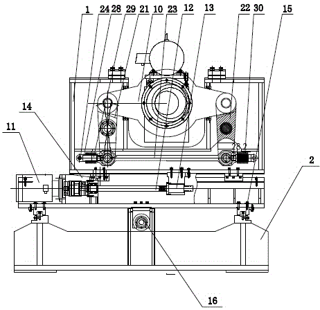
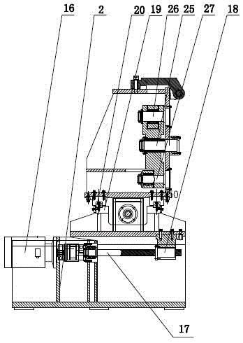
[0016] Such as Figure 1-3 As shown, the present invention is a composite pipe end welding seam grinding equipment, which is mainly used for grinding

[0017] The weld seam at the overlap between the surfacing layer and the liner makes a smooth transition. Including the frame 1, the base 2, the grinding mechanism arranged on the frame 1 and the grinding feeding mechanism arranged between the frame 1 and the base 2, the grinding mechanism and the grinding feeding mechanism are used together to realize Grinding of lap joints of pipe end sealing and welding layers in composite pipes.

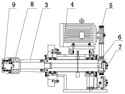
[0018] The grinding mechanism comprises a drive shaft 3, a frequency conversion motor 4 arranged above the drive shaft 3, an upper pulley 5 connected to the output end of the frequency conversion motor 4, and one end of the drive shaft 3 is sleeved with a lower pulley 6, an upper pulley 5...


PUM


Abstract

The invention discloses composite tube end surfacing layer weld joint polishing equipment which comprises a rack, a base, a polishing mechanism arranged on the rack and a polishing feeding mechanism arranged between the rack and the base; the polishing mechanism comprises a drive shaft, a variable frequency motor, an upper belt wheel, one end of the drive shaft is in cup joint with a lower belt wheel, the upper belt wheel and the lower belt wheel are connected through a belt, and the other end of the drive shaft is in cup joint with a grinding wheel and a contour wheel; the polishing feeding mechanism comprises a left-right feeding mechanism body, a front-rear feeding mechanism body and a linkage mechanism, a polishing fixing plate is hinged to the rack, and the drive shaft penetrates through the polishing fixing plate to be connected with the rack. The tube end surfacing layer weld joint polishing equipment is reasonable in structural design and convenient and fast to use, movement of the rack in the front-rear direction and the left-right direction is achieved through the arranged polishing feeding mechanism, the problem of circumferential jump of a steel pipe is solved through the arranged linkage mechanism, the problem of transition polishing of a grinding wheel can be effectively solved through the arranged grinding wheel and the contour wheel, and thus polishing precision and efficiency are improved.

Description

technical field [0001] The invention belongs to the technical field of mechanical equipment, and in particular relates to a welding seam grinding equipment for a cladding layer of a composite pipe end. Background technique [0002] Bimetal composite pipe usually puts a corrosion-resistant metal pipe inside another metal pipe, and fixes the two into one structure through expansion and end welding. There is an irregular transition step at the overlap of the welding layer. In order not to affect the subsequent use of the steel pipe, the step must be ground smoothly. The traditional grinding method is mostly manual grinding, and manual grinding mostly relies on the experience of workers to judge Grinding degree, this kind of grinding method has defects such as high grinding cost, low grinding precision, and long grinding time. Grinding existing defect, there is special grinding equipment on the market, but existing grinding equipment all exists and can't overcome the beating pr...

Claims


Application Information

Patent Timeline
IPC IPC(8): B24B9/04B24B47/20
CPCB24B9/04B24B47/20Y02P70/10
Inventor 陆明红吕林芳周建根邱锋
Owner 浙江久立特材科技股份有限公司湖州复合管分公司
Features
  • R&D
  • Intellectual Property
  • Life Sciences
  • Materials
  • Tech Scout
  • Unparalleled Data Quality
  • Higher Quality Content
  • 60% Fewer Hallucinations
Learn More