
Embedded parts for steel plate-concrete structures

A technology of steel plate concrete and embedded parts, which is applied in the direction of building structure and construction, can solve problems such as mechanical properties and construction differences, no invention of embedded parts, specification requirements, structure and construction technology, difficulties, etc., to avoid On-site welding, avoiding the effect of additional positioning tooling

Pending Publication Date: 2016-06-08
SHANGHAI NUCLEAR ENG RES & DESIGN INST CO LTD
View PDF3 Cites 5 Cited by
  • Summary
  • Abstract
  • Description
  • Claims
  • Application Information

AI Technical Summary

Problems solved by technology

[0002] The base material of conventional embedded parts is mostly reinforced concrete structure, which has the problems of conflict with steel bars and difficult positioning when installing embedded parts. The steel plate concrete structure itself is a new structural form, and its mechanical properties and construction are different from traditional concrete structures. There is a big difference, and there are also differences in the mechanical properties and construction of embedded parts based on steel plate concrete structure and embedded parts based on concrete structure.
Although there are construction examples of steel plate concrete structures, there are few normative provisions on steel plate concrete structures, and there are no related inventions, normative requirements, structures and construction techniques for embedded parts of steel plate concrete structures

Method used


Image

  • Embedded parts for steel plate-concrete structures
  • Embedded parts for steel plate-concrete structures
  • Embedded parts for steel plate-concrete structures

Examples


Embodiment Construction

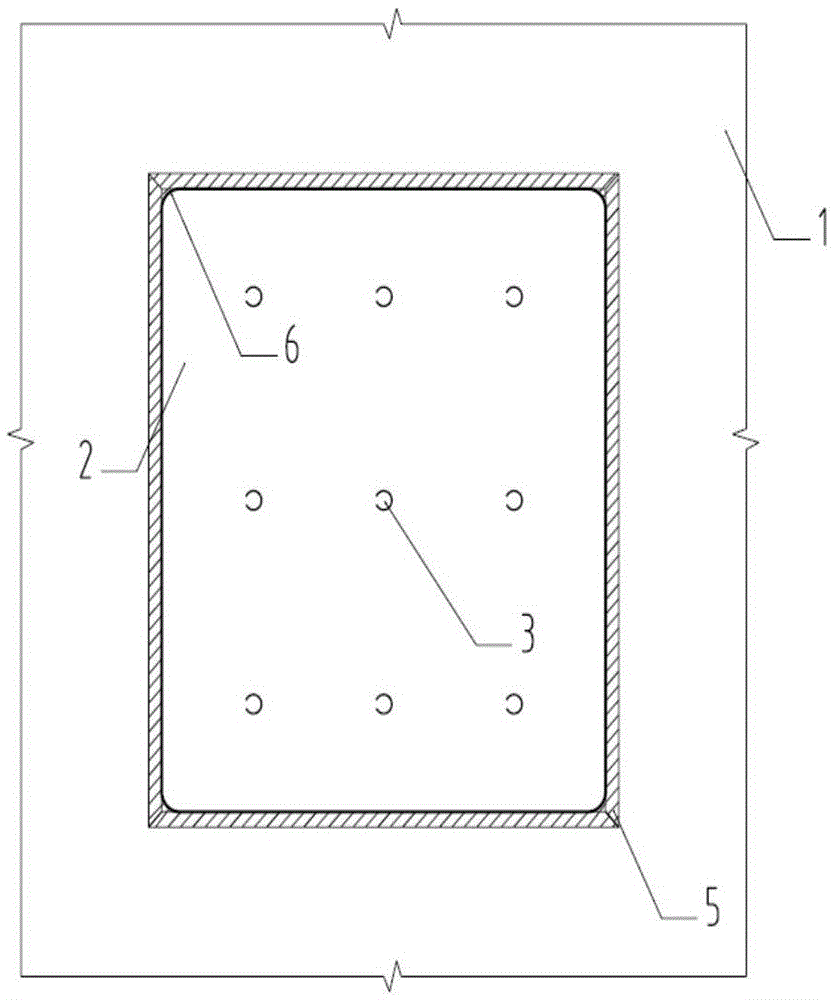
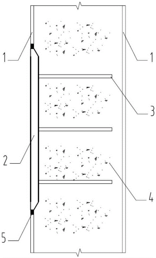
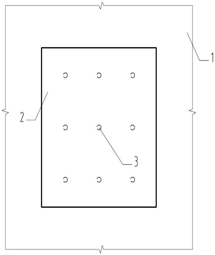
[0022] Attached below figure 1 , 2 The A-type embedded part of the present invention is further described with examples.

[0023] Step 1, prefabricating steel plate 1 of steel plate concrete in factory;

[0024] Step 2, prefabricate the steel panel 2 and the anchor bar 3 of the embedded part in the factory, fillet the four corners of the steel panel 2 with a radius of 25mm 6, and weld the steel panel 2 and the anchor bar 3 to complete the embedded part;

[0025] Step 3, when the difference in thickness between the steel plate 1 of the steel plate concrete and the steel panel 2 of the embedded part is more than 4mm, the edge of the steel panel is made with a bevel angle not greater than 1:2.5;

[0026] Step 4, after determining the position of the steel panel 2 of the embedded part on the steel plate 1 of the steel plate concrete, opening holes on the steel plate 1 to install the embedded part, and connecting the steel plate 1 and the steel panel 2 into a whole through the bu...


PUM

PropertyMeasurementUnit
Thicknessaaaaaaaaaa

Abstract

The invention discloses embedded parts for steel plate-concrete structures and solves the problems that as the base materials of most conventional embedded parts are of reinforced concrete structures, conflict with steel bars and difficult positioning are caused during installation of the embedded parts. The steel plate-concrete structure is a novel structural format per se, and has the mechanical property and construction, much different from those of a traditional concrete structure, so that the mechanical property and the construction of the embedded parts taking the steel plate-concrete structures as the base materials are different from those of the embedded parts taking the concrete structures as the base materials. The invention provides calculation evaluation criteria, structures and construction technology of the embedded parts for the steel plate-concrete structures, and provides embedded parts of three formats, which can be flexibly selected for use according to the stress characteristics, the structural requirements and the construction characteristics of the embedded parts; the embedded parts can be precast in a modular manner in factories along with steel plates of steel plate-concrete structures, field welding and field installation are prevented, and civilized construction and economical and environmental protection are achieved accordingly.

Description

technical field [0001] The invention belongs to the technical field of building structures, and in particular relates to embedded parts for steel plate concrete structures. Background technique [0002] The base material of conventional embedded parts is mostly reinforced concrete structure, which has the problems of conflict with steel bars and difficult positioning when installing embedded parts. Steel plate concrete structure itself is a new structural form, and its mechanical properties and construction are different from traditional concrete structures. There is a big difference, and there are also differences in the mechanical properties and construction of embedded parts based on steel plate concrete structure and embedded parts based on concrete structure. Although there have been construction examples of steel plate concrete structures, there are few normative provisions on steel plate concrete structures, and there are no related inventions, normative requirements,...

Claims


Application Information

Patent Timeline
IPC IPC(8): E04B1/41
CPCE04B1/41
Inventor 马波储艳春李韶平倪南李成王涛俞冬良
Owner SHANGHAI NUCLEAR ENG RES & DESIGN INST CO LTD
Learn More