
A binary plug nozzle plug center body cooling structure

A technology of cooling structure and plug-type nozzle, which is applied in the direction of jet propulsion devices, machines/engines, etc., can solve the problems of difficult cooling of the central body and restrictions on the arrangement of cold air pipelines, and achieve high utilization of cold air and good cooling effect

Active Publication Date: 2018-03-16
AECC SHENYANG ENGINE RES INST
View PDF9 Cites 0 Cited by
  • Summary
  • Abstract
  • Description
  • Claims
  • Application Information

AI Technical Summary

Problems solved by technology

[0002] The conventional binary plug nozzle has a plug center body at the outlet of the nozzle. The plug center body is in a high-temperature, high-speed jet flow environment. In order to protect the plug center body and improve the stealth ability, it is necessary to The plug-type central body is cooled; however, the working environment of the plug-type central body brings difficulties to the cooling of the central body; and because the plug-type central body is at the outlet of the nozzle, the layout of the cold air pipeline is limited

Method used


Image

  • A binary plug nozzle plug center body cooling structure
  • A binary plug nozzle plug center body cooling structure
  • A binary plug nozzle plug center body cooling structure

Examples


Embodiment 1

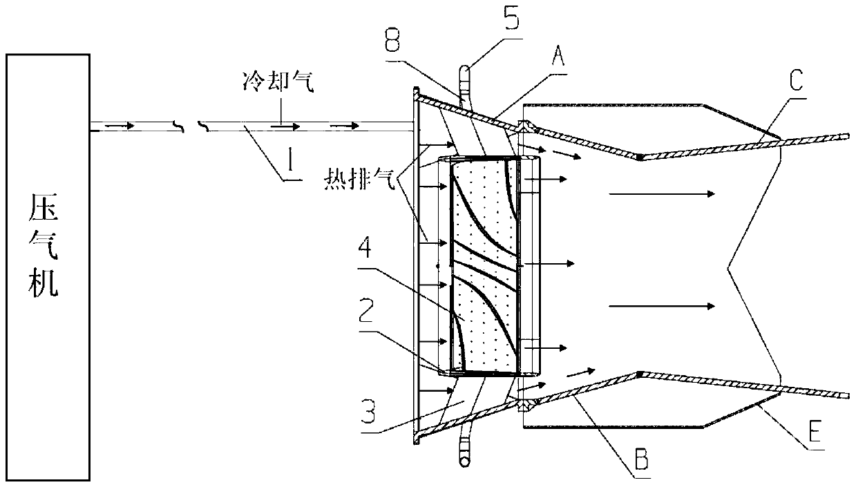
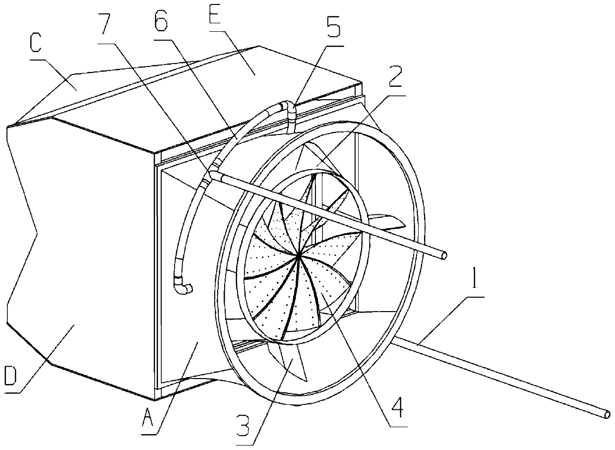
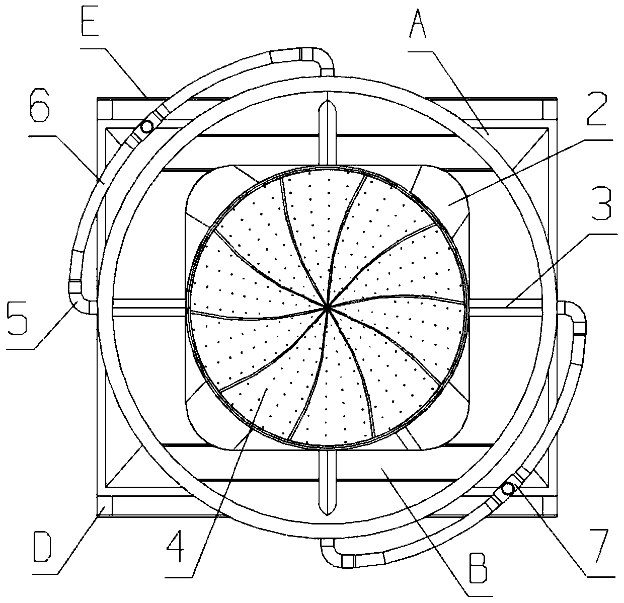
[0023] This embodiment provides a dual-plug nozzle plug-type center body cooling structure, which is characterized in that it includes a cold air pipeline, a thin-walled circular and square structure 2, a bracket 3 and a leaf-shaped structure 4 for shielding swirling flow;

[0024] Among them: the cold air pipeline includes air-inducing pipe 1, elbow 5, air-distributing pipe 6, tee joint 7 and air-guiding pipe 8; 8 enters the bracket 3, and then is introduced into the hollow structure of the thin-walled circular and square structure 2, and then the cooling air enters the cooling channel that blocks the swirling leaf-shaped structure 4, and finally flows out from the cooling air film hole against the wall of the swirling leaf-shaped structure 4. The structure forms a good cooling and protection.

[0025] The shielding swirl leaf-shaped structure 4 is arranged in the thin-walled circular square structure 2 along the circumferential direction of the cylinder wall, and the front a...

Embodiment 2

[0033] This embodiment provides a dual-plug nozzle plug-type center body cooling structure, which is characterized in that it includes a cold air pipeline, a thin-walled circular and square structure 2, a bracket 3 and a leaf-shaped structure 4 for shielding swirling flow;

[0034] Among them: the cold air pipeline includes air-inducing pipe 1, elbow 5, air distribution pipe 6, three-way joint 7 and air guide pipe 8; 8 enters the bracket 3, and then is introduced into the hollow structure of the thin-walled circular and square structure 2, and then the cooling air enters the cooling channel that blocks the swirling leaf-shaped structure 4, and finally flows out from the cooling air film hole against the wall of the swirling leaf-shaped structure 4. The structure forms a good cooling and protection.

[0035] The shielding swirl leaf-shaped structure 4 is arranged in the thin-walled circular square structure 2 along the circumferential direction of the cylinder wall, and the fro...

Embodiment 3

[0043] This embodiment provides a dual-plug nozzle plug-type central body cooling structure, which is characterized in that it includes a cold air pipeline, a thin-walled circular and square structure 2, a bracket 3 and a swirling leaf-shaped structure 4;

[0044] Among them: the cold air pipeline includes air-inducing pipe 1, elbow 5, air distribution pipe 6, three-way joint 7 and air guide pipe 8; 8 enters the bracket 3, and then is introduced into the hollow structure of the thin-walled circular and square structure 2, and then the cooling air enters the cooling channel that blocks the swirl leaf-shaped structure 4, and finally flows out from the cooling air film hole against the wall of the swirl leaf-shaped structure. The structure forms a good cooling and protection.

[0045] The shielding swirl leaf-shaped structure 4 is arranged along the circumference of the cylinder wall in the thin-walled circular square structure 2, and the front section and rear end section of the...


PUM


Abstract

A novel cooling structure for a plug type center body of a two-dimensional plug type nozzle comprises a cool air pipeline, a thin-wall round-to-square structure, supports and shielding rotational flow blade-shaped structures; the cool air pipeline comprises an air leading pipe, an elbow, an air distribution pipe, a three-way connector and an air guiding pipe; the front end of the air leading pipe is connected to an air compressor, high-pressure air flows to the air distribution pipe through the air leading pipe, enters the supports through the air guiding pipe and then is guided into the hollow structure of a cylinder wall of the thin-wall round-to-square structure, cool air enters cooling channels of the shielding rotational flow blade-shaped structures and finally flows out through cool air film holes in a wall adhesion mode, and the rotational flow blade-shaped structures are cooled and protected well; the shielding rotational flow blade-shaped structures are arranged in the thin-wall round-to-square structure in the circumferential direction of the cylinder wall, and the sections of the front ends of the shielding rotational flow blade-shaped structures and the sections of the rear ends of the shielding rotational flow blade-shaped structures are arranged in the circumferential direction. The novel cooling structure has the advantages that the shortcoming that cooling of plug type center bodies of conventional two-dimensional plug type nozzles is difficult is overcome, the utilization rate of the cool air is high, and the cooling effect is good.

Description

technical field [0001] The invention relates to the field of aeroengine nozzles, in particular to a dual-plug nozzle plug-type central body cooling structure. Background technique [0002] The conventional binary plug nozzle has a plug center body at the outlet of the nozzle. The plug center body is in a high-temperature, high-speed jet flow environment. In order to protect the plug center body and improve the stealth ability, it is necessary to The plug-type center body is cooled; however, the working environment of the plug-type center body brings difficulties to the cooling of the center body; and because the plug-type center body is at the outlet of the nozzle, the arrangement of the cold air pipeline is limited. Contents of the invention [0003] The purpose of the present invention is to make up for the defects of conventional binary plug nozzle plug center body cooling, and to provide a binary plug nozzle plug center body cooling structure. [0004] The present inv...

Claims


Application Information

Patent Timeline
Patent Type & Authority Patents(China)
IPC IPC(8): F02K1/78
Inventor 任利锋赵春生王殿磊
Owner AECC SHENYANG ENGINE RES INST
Learn More