Transmission shaft of heavy-duty speed reducer

A transmission shaft and reducer technology, applied in the field of transmission shafts, can solve problems such as unbalanced transmission torque, low transmission efficiency, and reduced reliability, and achieve the effect of torque balance and high transmission efficiency

Inactive Publication Date: 2016-06-08
彭芹
View PDF0 Cites 0 Cited by
  • Summary
  • Abstract
  • Description
  • Claims
  • Application Information

AI Technical Summary

Problems solved by technology

For large or heavy-duty reducers, due to the large transmission torque, if the key pins are still used for connection, the transmission torque will be unbalanced, unstable, and the tr

Method used


Image

  • Transmission shaft of heavy-duty speed reducer

Examples


Example Embodiment

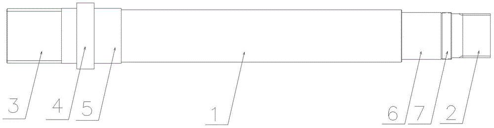
[0012] Such as figure 1 As shown, a transmission shaft of a heavy-duty reducer includes a transmission shaft body 1. One end of the transmission shaft body 1 is provided with a gear I2, and the other end is provided with a gear II3. Both the gear I2 and the gear II3 are connected to the transmission shaft body 1. Connect to each other to form a whole structure.

[0013] In this embodiment, the inner side of the gear I is set as the journal 7, and the inner side of the journal 7 is set as the bearing installation position I6; the inner side of the gear II3 is set as the limiting convex ring structure 4, and the inner side of the convex ring structure 4 is provided It is the bearing installation position Ⅱ5. The normal modulus of the gear I2 and the gear II3 is 5, the number of teeth is 22, 24 or 26, and the tooth profile angle is 30 degrees. In this embodiment, the number of teeth is preferably 24, the addendum height coefficient is 0.5, and the addendum clearance coefficient is...


PUM


Abstract

The invention relates to a transmission shaft of a heavy-duty speed reducer. The transmission shaft comprises a transmission shaft body. One end of the transmission shaft body is provided with a gear I, and the other end of the transmission shaft body is provided with a gear II. The gear I and the gear II are both connected with the transmission shaft body to form an integral structure. The inner side of the gear I is arranged to be a shaft neck, and the inner side of the shaft neck is arranged to be a bearing mounting position; the inner side of the gear II is arranged to be a limiting convex ring structure, and the inner side of the convex ring structure is arranged to be a bearing mounting position. The normal module of the gear I and the normal module of the gear II are both 5. The number of teeth of the gear I is 22, 24 or 26, and the number of teeth of the gear II is 22, 24 or 26. The tooth profile angle of the gear I and the tooth profile angle of the gear II are both 30 degrees. The transmission shaft body is made of a material comprising 42CrMo. The two ends of the transmission shaft body are provided with shaft end covers correspondingly. Compared with the prior art, the shaft ends of the transmission shaft are provided with the gears to form the integral structure, so that the transmission efficiency is high, and transmitted torque is balanced and stable. The transmission shaft is applicable to the large or heavy-duty speed reducer.

Description

technical field [0001] The invention relates to the technical field of transmission machinery, in particular to a transmission shaft of a heavy-duty reducer. Background technique [0002] At present, the existing transmission structure of the reducer generally includes a transmission shaft, a transmission gear and a pulley, and the transmission shaft, the transmission gear and the pulley are usually connected by key pins to transmit torque. For large or heavy-duty reducers, due to the large transmission torque, if the key pins are still used for connection, the transmission torque will be unbalanced, unstable, and the transmission efficiency will be low, and the transmission parts of the reducer are easily damaged, resulting in the failure of the reducer. Reduced service life and reduced reliability. Contents of the invention [0003] The purpose of the present invention is to provide a transmission shaft of a heavy-duty reducer with high transmission efficiency. The tran...

Claims


Application Information

Patent Timeline
IPC IPC(8): F16C3/02F16H55/17F16H55/08
Inventor 彭芹
Owner 彭芹
Why Eureka
Try Eureka