
Novel hanging arm applied to television set hanging frame

A TV, a new type of technology, applied in the direction of the machine/stand, supporting machine, mechanical equipment, etc., can solve the problems of TV falling, hidden safety hazards, and no installation, to prevent accidental falling, high safety, simple structure

Active Publication Date: 2016-06-08
宁波中易电子科技有限公司
View PDF9 Cites 4 Cited by
  • Summary
  • Abstract
  • Description
  • Claims
  • Application Information

AI Technical Summary

Problems solved by technology

Existing flat-panel TVs are generally installed on the wall with fixed brackets, which is not conducive to the movement or angle conversion of the flat-panel TV. In order to effectively solve this problem, various movable TV hangers have emerged as the times require. The panel is detachably connected, so there is a joint between the TV hanger and the wall panel, such as a card slot, etc.
Some of the existing card slots are not provided with a locking structure, which has potential safety hazards; and although some are provided with a locking structure, such as the Chinese invention patent "A Flat-panel TV Rack" whose patent number is ZL201110118740.1 (notification number is CN102767671B). Hanging foot assembly" discloses such a hanging foot assembly of a flat-panel TV rack, including a hanging foot, at least a through hole is provided under itself; It is arranged in the installation through hole of the hanging foot; a sliding buckle is provided with a lock, assembled outside the installation through hole of the hanging foot, and connected with the stopper, so that the sliding buckle can move up and down; a spring is placed in the stopper Between the block and the installation through hole of the hanging foot, the block has a tendency to move upwards; a pull piece is connected to the block to operate the block to move up and down
When in use, first install the TV on the hanging feet, and then hang the hanging feet on the wall board, the spring can make the stopper and the sliding buckle automatically block the wall board together, so as to realize the installation of the TV, and then remove the TV When using the pull piece, pull the pull piece to make the block move downward. Because the slide buckle is connected with the block, the block drives the slide buckle to move downward at the same time. At this time, the lock hook on the slide buckle produces a downward movement Displacement, so that the lock hook on the slider is separated from the wallboard to achieve the unlocking function. At this time, the TV can be removed. Although the locking device is convenient for disassembly and installation of the TV, when the TV is installed , when people sit on the sofa and watch TV, they often like to pull the TV down at an angle to get the best viewing effect. At this time, the TV is still hung on the wallboard through the lock. The weight of the TV is relatively light, and it is impossible to have sufficient strength, that is, the TV frame may still be loose when locked on the TV, and the TV is easy to fall due to the unlocking of the lock. This situation is also likely to happen to children. Driven by the driver, he is very likely to pull the pull member to unlock the lock, so that the TV will fall on the child and cause accidents. Therefore, in order to improve the safety of TV locking, it is necessary to hang the TV with this structure. frame for further improvement

Method used


Image

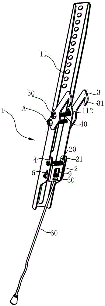
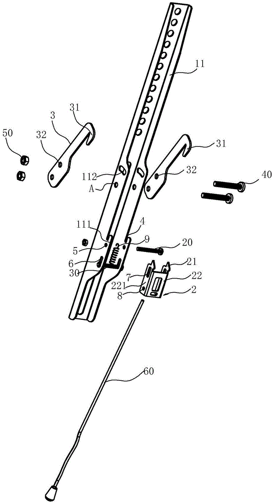
  • Novel hanging arm applied to television set hanging frame
  • Novel hanging arm applied to television set hanging frame
  • Novel hanging arm applied to television set hanging frame

Examples


Embodiment Construction

[0020] The present invention will be further described in detail below in conjunction with the accompanying drawings and embodiments.

[0021] The novel hanging arm used for the TV hanger constitutes a TV hanger together with the wallboard 10 during use, and is usually provided with left and right two hanging arms, and the left and right hanging arms can move relative to the wallboard 10 To suit different TV sizes, the left and right hanging arms have the same structure, and the following descriptions for the left hanging arm are also applicable to the right hanging arm.

[0022] like Figure 1~5 As shown, the left hanging arm includes a hanging arm body 1 and a locking plate 2, and the hanging arm body 1 has a connecting arm 11 for installing a TV set. 3 and the lower end is provided with a locking piece 2, the hook 3 has a first hook 31 with an opening downward facing the wallboard 10, and the locking piece 2 has a second hook 21 with an opening upward, the first hook 31 an...


PUM


Abstract

The invention relates to a novel hanging arm applied to a television set hanging frame. The novel hanging arm comprises a hanging arm body and a locking sheet, wherein the hanging arm body is provided with a connection arm, a hook and the locking sheet; the hook is provided with a first hook part while the locking sheet is provided with a second hook part; an elastic part is arranged on the locking sheet; the novel hanging arm is characterized in that a third hook part with an opening formed upwardly and a height being lower than that of the second hook part is also arranged at the position near the locking sheet of the connection arm; the locking sheet is pulled in a direction far away from a wallboard of the connection arm to move down, namely the bottom of the wallboard can completely fall into the third hook part and cannot be separated from the third hook part under the locking action of the second hook part. Compared with the prior art, the novel hanging arm has the advantages that the limitation that only the first hook part of the hook at the upper end of the connection arm and the second hook part of the locking sheet can be used for locking the wallboard after the television set is mounted in the prior art is broken through; when the upper part of the connection arm is pulled at a certain angle in a direction far away from the wallboard, the wallboard can fall into the third hook part along upward movement of the hanging arm and the locking sheet can lock the wallboard again at the same time, so that the dual-insurance effect can be achieved.

Description

technical field [0001] The invention relates to a TV hanging rack, in particular to a TV hanging arm equipped with a safety device, which can prevent children from pulling the TV hanging arm by mistake. Background technique [0002] With the continuous improvement of people's living standards, flat-panel TVs have begun to replace desktop TVs and have entered thousands of households. How to effectively install flat panel TVs and improve visual enjoyment has become another important goal that people want to pursue. Existing flat-panel TVs are generally installed on the wall with fixed brackets, which is not conducive to the movement or angle conversion of the flat-panel TV. In order to effectively solve this problem, various movable TV hangers have emerged as the times require. The panel is detachably connected, so the TV hanger and the wall panel have a joint, such as a card slot. Some of the existing card slots are not provided with a locking structure, which has potential...

Claims


Application Information

Patent Timeline
IPC IPC(8): F16M13/02F16M11/04
CPCF16M11/04F16M13/02F16M2200/02
Inventor 叶笑笑
Owner 宁波中易电子科技有限公司
Learn More