Swing arm type underslung crane
A suspension crane and swing arm type technology, which is applied in the direction of load-carrying block, traveling mechanism, load-hanging element, etc., can solve the problems of reducing the applicability of use, reducing the practicality and convenience of use, and reducing the scope of use, etc.
- Summary
- Abstract
- Description
- Claims
- Application Information
AI Technical Summary
Problems solved by technology
Method used
Image
Examples
Embodiment 1
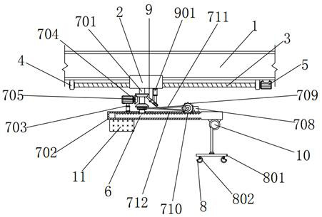
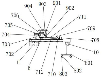
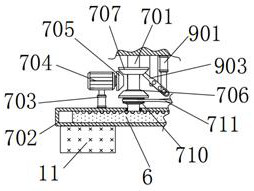
[0032] A swing-arm type suspension crane, comprising a beam 1, a sliding seat 2 is fitted in the gap at the bottom of the beam 1, a screw 3 is threaded under the inner wall of the sliding seat 2, and a bracket 4 is provided on the left and right sides of the screw 3, and the bracket 4 The inner wall is rotationally connected to both sides of the outer wall of the screw rod 3, and the top of the bracket 4 is fixedly connected to the left and right sides of the bottom of the beam 1. The right side of the bracket 4 is provided with a first motor 5, and the model of the first motor 5 is ECMA-E11320RS. The output end of the first motor 5 is fixedly connected with the right end of the screw rod 3, the top of the first motor 5 is fixedly connected with the bottom right side of the crossbeam 1, a swing arm 6 is arranged below the slide seat 2, and the left side of the swing arm 6 is below A counterweight 11 is provided, and an electric hoist 10 is fixedly connected to the right side of...
Embodiment 2
[0035] As an option, see figure 1 , 2 , 4 and 6, swing arm type suspension crane, the rope end of electric hoist 10 is provided with hanger assembly 8, and hook assembly 8 comprises horizontal plate 801, hook 802, baffle plate 803 and compression spring 804, the bottom center of horizontal plate 801 and The rope ends of the electric hoist 10 are fixedly connected, and a hook 802 is provided below the horizontal plate 801. The tops of the two hooks 802 are fixedly connected to the left and right sides of the bottom of the horizontal plate 801. The hooks 802 are symmetrically distributed about the horizontal plate 801, so that the design is convenient. The lifting object is hooked, the inside of the hook 802 is provided with a baffle 803, the top of the baffle 803 is rotatably connected with the top of the inner wall of the hook 802, the outer end of the baffle 803 is fixedly connected with the inner wall of the hook 801, and the top of the baffle 803 A compression spring 804 is ...
Embodiment 3
[0038] As an option, see Figure 1-3 , a swing arm type suspension crane, the bottom right side of the slide seat 2 is provided with a clamping assembly 9, and the clamping assembly 9 includes a second cylinder 901, a short rod 902, a rotating rod 903 and a pole 904, and the top of the second cylinder 901 is connected to the The right side of the bottom of the sliding seat 2 is fixedly connected, and a short rod 902 is fixedly connected under the front of the telescopic rod of the second cylinder 901, and a rotating rod 903 is arranged on the front of the short rod 902, and the rotating rod 903 is set correspondingly to the positions of the two driven wheels 707 , the rotating rod 903 can play a clamping and limiting effect on the two driven wheels 707, the preset through groove on the right side of the front of the rotating rod 903 is matched with the outer wall of the short rod 902, and the middle section of the front of the rotating rod 903 is rotationally connected with a s...
PUM
 Abstract
Description
Claims
Application Information
 - R&D
- Intellectual Property
- Life Sciences
- Materials
- Tech Scout
- Unparalleled Data Quality
- Higher Quality Content
- 60% Fewer Hallucinations
Browse by: Latest US Patents, China's latest patents, Technical Efficacy Thesaurus, Application Domain, Technology Topic, Popular Technical Reports.
© 2025 PatSnap. All rights reserved.Legal|Privacy policy|Modern Slavery Act Transparency Statement|Sitemap|About US| Contact US: help@patsnap.com


