
Drainage and drag reduction device in the guide tube, guide tube and shell-and-tube heat exchanger

A technology of drag reduction device and guide tube, applied in the direction of heat exchanger type, heat exchanger shell, indirect heat exchanger, etc., can solve the problem of reduced pressure bearing capacity of heat exchanger shell side and unreasonable design of guide tube structure , the complex structure of the guide tube, etc., to achieve the effect of eliminating the stagnation area, simple structure and low cost

Active Publication Date: 2017-11-07
MAOMING MAOGANG ELECTRIC POWER EQUIP FACTORY
View PDF5 Cites 0 Cited by
  • Summary
  • Abstract
  • Description
  • Claims
  • Application Information

AI Technical Summary

Problems solved by technology

However, due to the unreasonable structural design of the existing guide tube, the guide tube blocks the fluid, so that a fluid stagnation area is formed in the guide tube, and the fluid resistance is relatively large
On the other hand, due to the complex structure of the guide tube, the processing is difficult, the equipment cost is high, and the pressure bearing capacity of the shell side of the heat exchanger is reduced

Method used


Image

  • Drainage and drag reduction device in the guide tube, guide tube and shell-and-tube heat exchanger
  • Drainage and drag reduction device in the guide tube, guide tube and shell-and-tube heat exchanger
  • Drainage and drag reduction device in the guide tube, guide tube and shell-and-tube heat exchanger

Examples


Embodiment 1

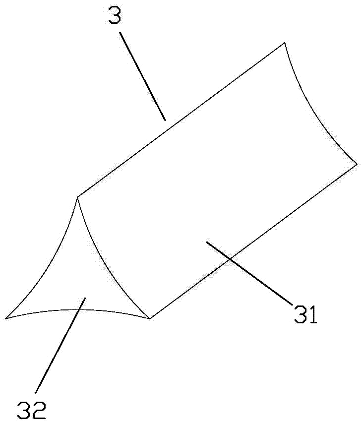
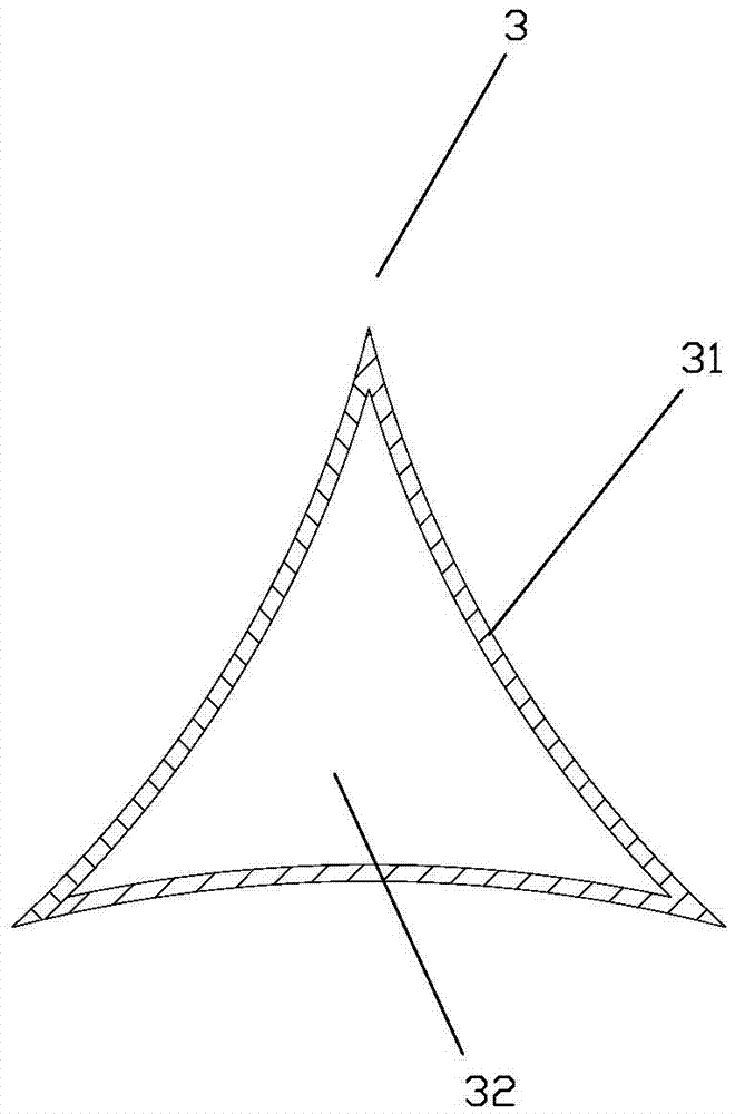
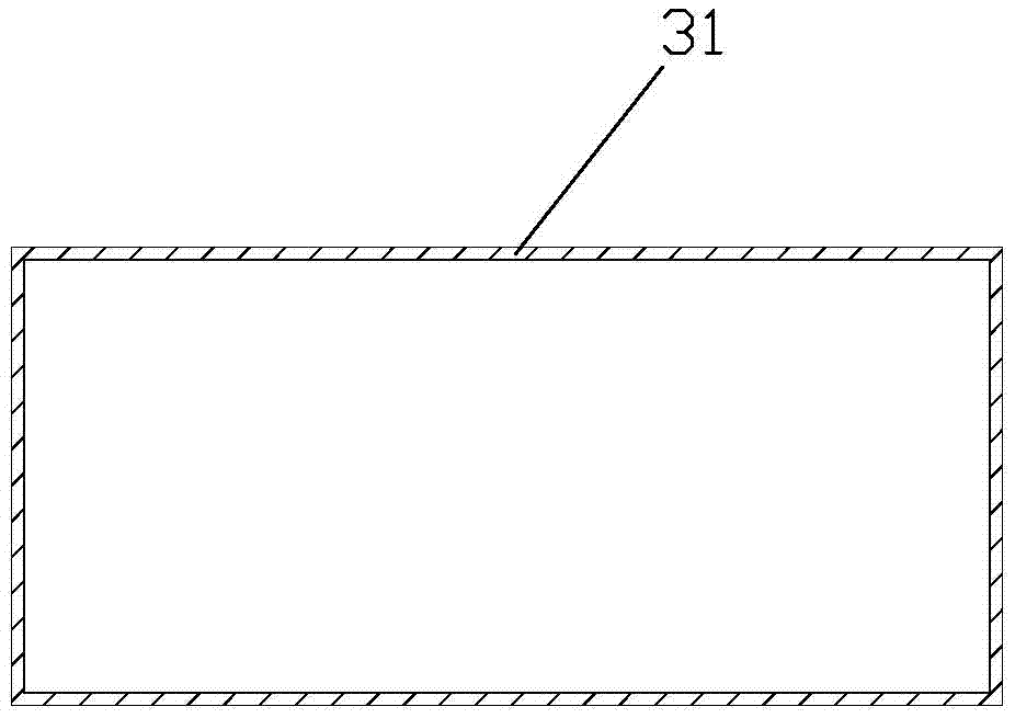
[0034] The guide tube of this embodiment is as Figure 1 to Figure 5 As shown, the guide tube 2 includes a guide tube inner shell 21 and a guide tube outer shell 22, the guide tube shell 22 is provided with a shell-side inlet 23, and the guide tube 2 is provided with a drainage drag reducing device 3, and the drainage drag reducing device 3 is arranged along the axial direction of the inner shell 21 of the guide tube, and the drainage and drag reduction device 3 is a closed structure formed by splicing two arc-shaped plates 31 and two side plates 32 . Among them: the two arc-shaped plates 31 and the two side plates 32 are symmetrically arranged, the upper ends of the two arc-shaped plates 31 are welded, the lower ends of the two arc-shaped plates 31 are respectively welded to the inner shell 21 of the guide tube, and the two arc-shaped plates The opposite side ends of the plate 31 are respectively welded to the corresponding side plates 32, and the arc surfaces of the two arc ...

Embodiment 2

[0042] The shell-and-tube heat exchanger of the present embodiment, such as Figure 4 and Figure 5 As shown, including the housing 1, the inlet 11 and the outlet 12 of the housing 1 are provided with a guide tube 2, and the guide tube 2 at the inlet 11 of the housing 1 is provided with a drainage and drag reduction device 3. The structure of the drainage drag reducing device 3 is exactly the same as that of the first embodiment.

[0043]When the fluid enters the guide tube 2, the fluid flows to both sides through the two arc-shaped plates 31, and its scour resistance is dispersed, so that the fluid distribution is uniform and the vertical scour is reduced, so that the irregular fluid changes after entering the guide tube 2 Forming a regular fluid can stabilize the flow field and reduce fluid flow resistance, and avoid the huge fluid resistance borne by the guide tube 2, reducing the impact of the fluid on the heat exchange tube 4; on the other hand, this The invention can e...


PUM


Abstract

The invention relates to the technical field of tube-shell-type heat exchangers, in particular to a flow guiding and resistance-reducing device in a flow guiding barrel, the flow guiding barrel and a tube-shell-type heat exchanger, wherein the flow guiding and resistance reducing device is arranged along the axial direction of the inner shell of the flow guiding barrel; the flow guiding and resistance reducing device is of a closed structure spliced by two arc-shaped plates and two side plates; the upper ends of the two arc-shaped plates are connected; the lower ends of the two arc-shaped plates are separately fixed on the inner shell of the flow guiding barrel; the two opposite side ends of the two arc-shaped plates are separately fixedly connected with the corresponding side plate; and the arc-shaped surfaces of the two arc-shaped plates are both bent toward the inner sides. Compared with the prior art, the flow guiding and resistance-reducing device is advantaged in that the retention area of fluid in the flow guiding barrel is eliminated; the flowing resistance is reduced; and the energy-saving effect is good; the flow guiding and resistance-reducing device has the advantages of being simple in structure and convenient for manufacture; and the flow guiding and resistance-reducing device can be widely applied to heat exchangers in the oil industry, the chemistry industry, the electricity industry and the like.

Description

technical field [0001] The invention relates to the technical field of shell-and-tube heat exchangers, in particular to a drainage and drag reduction device in a draft tube, a draft tube and a shell-and-tube heat exchanger. Background technique [0002] At present, in my country's petrochemical and other industries, heat exchange equipment accounts for more than 30% of equipment investment. Among heat exchange equipment, shell and tube heat exchangers are used the most. Therefore, improving the efficiency of heat exchangers is beneficial to energy saving in the chemical industry. Emission reduction and efficiency improvement are very important. [0003] The traditional shell-and-tube heat exchanger adopts a smooth circular tube and a single-bow baffle support structure. The fluid flows perpendicular to the axial direction of the tube on the shell side, and there is a large flow and heat transfer in the front and rear areas of the baffle. The dead zone reduces the overall hea...

Claims


Application Information

Patent Timeline
Patent Type & Authority Patents(China)
IPC IPC(8): F28F9/22F28D7/16
CPCF28D7/16F28D7/1646F28F9/22F28F2009/222F28F2250/04Y02P20/10
Inventor 李权王新婷刘伟刘志春吕圣杰刘光辉蓝月华陈瑾张秀红全迪锋
Owner MAOMING MAOGANG ELECTRIC POWER EQUIP FACTORY
Learn More