Supercharge Your Innovation With Domain-Expert AI Agents!

Detection system of liquid flow position and detection method thereof

A detection system and liquid flow technology, applied in the field of sensing, can solve the problems that the measurement method is difficult to apply, can only be described qualitatively, and cannot obtain quantitative indicators, etc.

Active Publication Date: 2016-06-08
林成凡
View PDF4 Cites 1 Cited by
  • Summary
  • Abstract
  • Description
  • Claims
  • Application Information

AI Technical Summary

Problems solved by technology

[0003] Regardless of the flow form of the liquid flow, to clearly understand the law of its trajectory change, it is necessary to determine the position of the liquid flow, especially to obtain the position of the falling liquid flow on the detection plane, such as on many cavity parts For the processed small hole, it is necessary to judge whether the cavity part and the small hole processed are qualified. Since the part belongs to the cavity part, the traditional measurement method is difficult to apply. Two methods are often used in actual production: visual inspection method and standard rod method
The visual method is to let the liquid flow of a certain rated pressure be ejected from the small hole, and observe the position of the liquid flow with the eyes to distinguish the trajectory change. Because the resolution line of the human eye at the distance of clear vision is 0.07mm, this The measurement accuracy of the first method is low, and it can only be described qualitatively, and quantitative indicators cannot be obtained; the standard rod method is to insert a small standard rod into the small hole of the part, and simulate the axis of the liquid flow by measuring the axis of the standard rod. Due to the limitation of other factors, the measurement work is time-consuming and laborious, and the results are scattered and the accuracy is low.
[0004] At present, there is no detection system and detection method that can quantify and efficiently detect the liquid flow position to meet the demand.

Method used


Image

  • Detection system of liquid flow position and detection method thereof
  • Detection system of liquid flow position and detection method thereof

Examples


Embodiment Construction

[0023] Below in conjunction with accompanying drawing and embodiment, content of the invention will be further described:

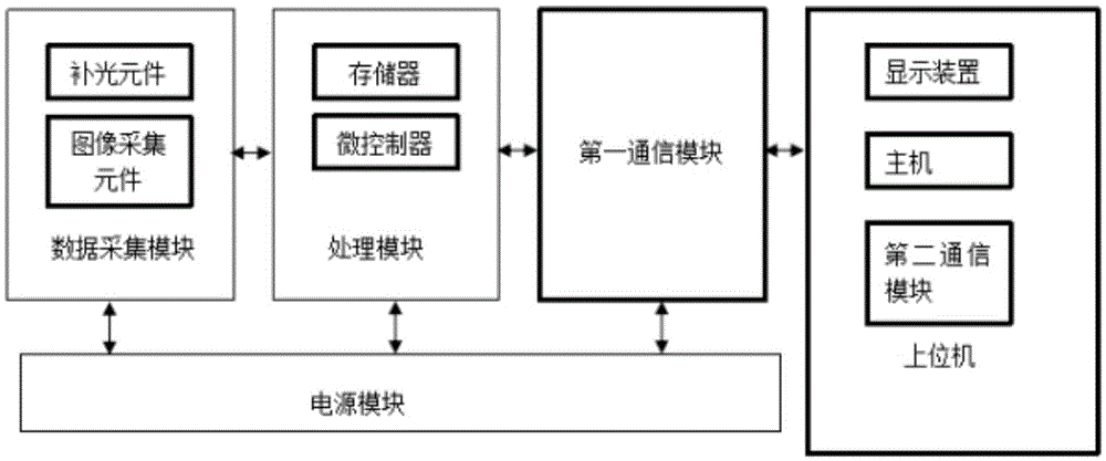
[0024] Such as figure 1 and figure 2 As shown, the detection system of the liquid flow position, the detection system of the liquid flow position includes a data acquisition module, a processing module, a communication module, a host computer and a power supply module;

[0025] in:

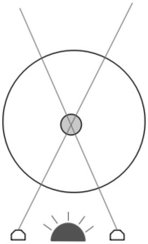
[0026] The data acquisition module includes an image acquisition element and a supplementary light element assigned to the image acquisition element. The number of the image acquisition elements is two, and is used to collect liquid flow under natural light or light of a specific wavelength provided by the supplementary light element. The reflected light signal to further judge the position of the liquid flow;

[0027] A processing module, which includes a microcontroller, the microcontroller is connected to the image acquisition element and the memory;

[0028] A commun...


PUM


Abstract

The invention discloses a detection system of liquid flow position and a detection method thereof. The detection system comprises a data collection module, a processing module, a communication module, an upper computer and a power module, wherein the data collection module comprises image collection elements and a light supplementing element for the image collection elements; two image collection elements are provided and used for collecting the reflected light signals of the liquid flow under natural light or specific-wavelength light provided by the light supplementing element so as to further judge the liquid flow position; the processing module comprises a microcontroller which is connected with the image collection elements and a memory; the communication module comprises a first communication module which is connected with the microcontroller; the upper computer comprises a host, a display device and a second communication module; and the power module is used for supplying power to the data collection module, the processing module, the communication module and the upper computer. Through the detection system of liquid flow position and the detection method thereof, the position of the falling liquid flow on a detection plane can be obtained.

Description

technical field [0001] The invention belongs to the field of sensing technology, and in particular relates to a liquid flow position detection system and a detection method thereof, in particular to a detection system and a detection method for obtaining the position of a falling liquid flow on a detection plane. Background technique [0002] Liquid flow, as a common working fluid in various fields of industry, often has fluidity, and the flow form of liquid flow is also distinguished: if the flow rate is very slow, the liquid flow will flow in layers without mixing with each other, which is laminar flow; if When the flow velocity increases and becomes faster and faster, the liquid flow begins to fluctuate. This situation is called transition flow; when the flow velocity continues to increase, the streamline cannot be clearly distinguished, and many eddies will appear. This is turbulent flow, also known as chaotic flow. flow, turbulence or turbulence. [0003] Regardless of...

Claims


Application Information

Patent Timeline
Patent Type & Authority Applications(China)
IPC IPC(8): G01B11/00
CPCG01B11/00
Inventor 林成凡缪兆伟周围
Owner 林成凡
Features
  • R&D
  • Intellectual Property
  • Life Sciences
  • Materials
  • Tech Scout
  • Unparalleled Data Quality
  • Higher Quality Content
  • 60% Fewer Hallucinations
Learn More