A 3ptt-2r series-parallel CNC machine tool servo system fault prediction device and method based on residual error observer
A 3PTT-2R, CNC machine tool technology, applied in general control systems, control/adjustment systems, instruments, etc., can solve problems such as false positives and false negatives, easy to cause false positives and false negatives, and low accuracy of fault parameter estimation. It achieves the effects of small calculation amount, improved effectiveness, and convenient real-time fault prediction
- Summary
- Abstract
- Description
- Claims
- Application Information
AI Technical Summary
Problems solved by technology
Method used
Image
Examples
specific Embodiment approach 1
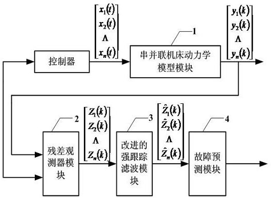
[0019] Specific implementation mode one: the following combination figure 1 Describe this embodiment, a 3PTT-2R series-parallel CNC machine tool servo system fault prediction device based on a residual observer in this embodiment, the purpose is to solve the problem of fault prediction purely using the prediction state, and at the same time, the non-linear filter has no The estimation accuracy is not high, and it is easy to cause false positives and false negatives. Therefore, the 3PTT-2R serial-parallel CNC machine tool servo system fault prediction device of the present invention includes a 3PTT-2R serial-parallel CNC machine tool dynamic model module, a residual observer module, an improved strong tracking filter module and a fault prediction module.
[0020] The 3PTT-2R serial-parallel CNC machine tool dynamics module constructs a serial-parallel CNC machine tool dynamics model based on the state signals such as the speed output by the controller, and outputs signals such ...
specific Embodiment approach 2
[0023] Specific implementation mode two: the following combination figure 1 Describe this embodiment, this embodiment is to do further explanation to Embodiment 1: the serial-parallel machine tool dynamics model that module 1 constructs is:
[0024] x(k+1)=A(k,x(k)) x(k)+Bu(k)
[0025] Among them, the state vector x(k), input vector u(k), output vector y(k) and coefficient matrix are:
[0026] x(k)=[I d (k)I q (k) ω(k) θ(k) T L (k) υ(k)] T ,
[0027] u(k)=[U d (k)U q (k)], y(k)=[I d (k)I q (k)],
[0028]
[0029] a 12 =T c ω(k);a 13 =T c I q (k); a 21 =-T c ω(k);
[0030]
[0031]
[0032] The observation equation can be written as:
[0033] y(k+1)=Cx(k+1)
[0034] in,
specific Embodiment approach 3
[0035] Specific implementation mode three: the following combination figure 1 Describe this embodiment, this embodiment is a further description of Embodiment 1: the residual observer equation constructed by the residual observer module 2 is:
[0036]
[0037] in, is the residual matrix, and F 1 =(I-C)A,F 2 =(I-C)B.
PUM
 Abstract
Description
Claims
Application Information
 - R&D
- Intellectual Property
- Life Sciences
- Materials
- Tech Scout
- Unparalleled Data Quality
- Higher Quality Content
- 60% Fewer Hallucinations
Browse by: Latest US Patents, China's latest patents, Technical Efficacy Thesaurus, Application Domain, Technology Topic, Popular Technical Reports.
© 2025 PatSnap. All rights reserved.Legal|Privacy policy|Modern Slavery Act Transparency Statement|Sitemap|About US| Contact US: help@patsnap.com


