

Electric automobile charging system for three-dimensional parking lots
A three-dimensional parking lot and electric vehicle technology, applied in the direction of electric vehicle charging technology, electric vehicles, buildings where cars are parked, etc., can solve the problems of inability to charge electric vehicles, achieve convenient charging operations, improve safety and reliability, The effect of ensuring charging safety
- Summary
- Abstract
- Description
- Claims
- Application Information
AI Technical Summary
Problems solved by technology
Method used
Image

Examples
Embodiment Construction
[0035] In order to make the purpose, technical solutions and advantages of the embodiments of the present invention clearer, the technical solutions in the embodiments of the present invention will be clearly and completely described below in conjunction with the drawings in the embodiments of the present invention. Obviously, the described embodiments It is a part of embodiments of the present invention, but not all embodiments. Based on the embodiments of the present invention, all other embodiments obtained by persons of ordinary skill in the art without creative efforts fall within the protection scope of the present invention.
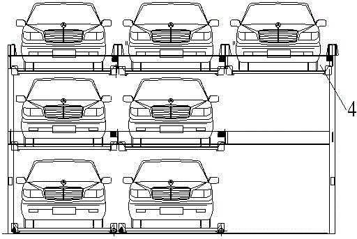
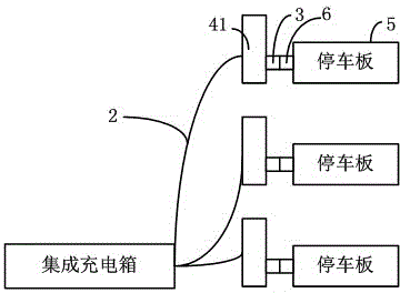
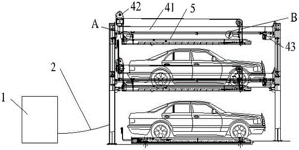
[0036] Such as Figure 1-3 As shown, the electric vehicle charging system in the three-dimensional parking lot of this embodiment includes an integrated charging box 1, wherein the integrated charging box 1 outputs several charging cables 2, and the ends of the charging cables 2 are connected to the first docking device 3 on the storage space of t...
PUM
 Abstract
Description
Claims
Application Information