
A Comparator Circuit with Clamping Function

A comparator circuit and comparator technology, applied in the field of circuits, can solve the problems of large variation range of opening voltage value, loss of clamping effect, limited application voltage range, etc., and achieve the effect of avoiding lining bias effect and wide voltage application range

Active Publication Date: 2019-01-08
CRM ICBG (WUXI) CO LTD
View PDF4 Cites 0 Cited by
  • Summary
  • Abstract
  • Description
  • Claims
  • Application Information

AI Technical Summary

Problems solved by technology

The disadvantage of this circuit structure is: VF1 needs to have sufficient load capacity to prevent the voltage deviation of VF1 itself due to insufficient drive capacity and lose the clamping effect
However, the disadvantage of this structure is: because of the lining bias effect caused by the difference between the substrate voltage and the source voltage of the MOS transistor, the turn-on voltage value of the MOS will vary widely, and the application voltage range is limited.

Method used


Image

  • A Comparator Circuit with Clamping Function
  • A Comparator Circuit with Clamping Function
  • A Comparator Circuit with Clamping Function

Examples


Embodiment 1

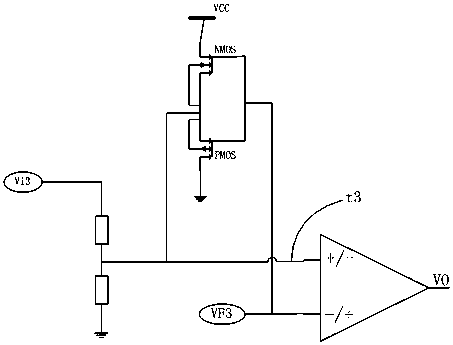
[0017] Embodiment 1: The positive phase input terminal of the comparator in this embodiment is connected to the sources of the NMOS transistor and the PMOS transistor, the input terminal is connected to the input voltage (Vi3) through a resistor, and its negative phase input terminal is connected to the reference voltage ( VF3), assuming that the turn-on voltage of the PMOS transistor is Vthp, and the turn-on voltage of the NMOS transistor is Vthn, then the voltage at the input terminal t3 is limited within the voltage range of (VF3-Vthn)~(VF3+Vthn) partial effect.

Embodiment 2

[0018] Embodiment 2: The negative phase input terminal of the comparator in this embodiment is connected to the sources of the NMOS transistor and the PMOS transistor, the input terminal is connected to the input voltage (Vi3) through a resistor, and its positive phase input terminal is connected to the reference voltage ( VF3), assuming that the turn-on voltage of the PMOS transistor is Vthp, and the turn-on voltage of the NMOS transistor is Vthn, then the voltage at the input terminal t3 is limited within the voltage range of (VF3-Vthn)~(VF3+Vthn) partial effect.

[0019] The invention is a novel comparator circuit with a clamping function. The circuit not only avoids the higher requirement on the driving ability of the reference voltage, but also effectively overcomes the lining offset effect, and the voltage application range is wider.


PUM


Abstract

The invention discloses a circuit, and in particular relates to a comparator circuit having a clamping function. The comparator circuit comprises a NMOS transistor, a PMOS transistor and a comparator; the source of the NMOS transistor is short-circuited with a substrate; the drain of the NMOS transistor is connected with a power supply; the source of the PMOS transistor is short-circuited with the substrate; the drain of the PMOS transistor is connected with the ground; one input end of the comparator is connected to the sources of the NMOS transistor and the PMOS transistor; the input end of the comparator is connected to input voltage through resistance; another input end of the comparator is connected to reference voltage; and the output end of the comparator is connected with an external circuit. By mans of the circuit structure disclosed by the invention, relatively high requirements on the reference voltage driving capability is avoided; furthermore, the substrate deviation effect can be effectively overcome; and the voltage application range is relatively wide.

Description

technical field [0001] The invention relates to a circuit, in particular to a comparator circuit with a clamping function. Background technique [0002] In some electronic drive systems, the control circuit needs to use external signals to make correct judgments, such as phase detection, zero-crossing detection, etc. In the zero-crossing detection circuit, a comparator is usually used as a detection technical solution. And because the detection circuit is an integrated circuit, its own withstand voltage is limited, and the fluctuation range of the external input signal may exceed the withstand voltage range of the circuit, causing damage to the circuit, so a clamping circuit is usually set at the position of the input signal for protection. [0003] There are two common clamping circuit methods, which are as follows: [0004] (1) The first is a diode clamp circuit, as attached figure 1 As shown, the circuit is composed of a diode and a comparator. The positive phase input ...

Claims


Application Information

Patent Timeline
Patent Type & Authority Patents(China)
IPC IPC(8): H03K5/22
CPCH03K5/22
Inventor 刘卫中王效张明丰蒋亚平孔祥艺唐颖炯王娜芝牛瑞萍吴燕
Owner CRM ICBG (WUXI) CO LTD
Learn More