Modular light emitting diode lighting system

A technology of LED lighting and LED light strips, which can be used in lighting devices, fixed lighting devices, lighting auxiliary devices, etc., and can solve problems such as wasting time and error-prone

Inactive Publication Date: 2016-06-08
布莱恩·巴雷特
View PDF11 Cites 12 Cited by
  • Summary
  • Abstract
  • Description
  • Claims
  • Application Information

AI Technical Summary

Problems solved by technology

However, the welding requirements for LED light strips/light strips or powe

Method used


Image

  • Modular light emitting diode lighting system
  • Modular light emitting diode lighting system
  • Modular light emitting diode lighting system

Examples


Embodiment Construction

[0051] The present invention will be further described below with reference to the accompanying drawings and embodiments, which are preferred embodiments of the present invention.

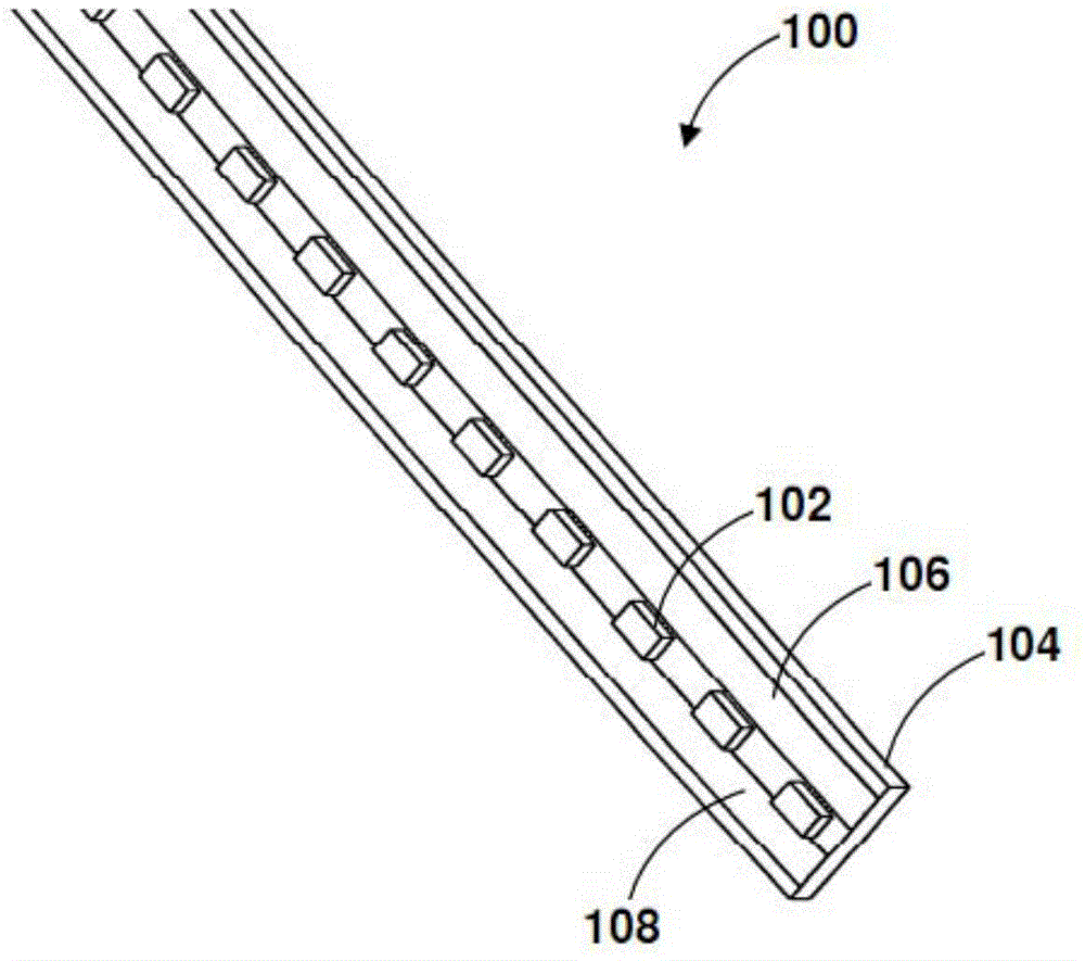
[0052] Please refer to the attached figure 1 , with figure 1 It is the LED light bar 100 of the present invention. The LED light bar 100 includes a substrate 104 , and the substrate 104 includes two sides, one or more LED lamp beads 102 and two conductive strips 106 and 108 . The substrate 104 is a rigid insulator, or an insulated conductor, or a semiconductor, or a conductive plane. Two or more LED lamp beads 102 and two parallel conductive strips 106 and 108 are mounted on one side of the substrate 104 , so that the LED lamp beads 102 are electrically connected to the conductive strips 106 and 108 . The conductive strips 106 and 108 are mounted on the same side or opposite sides of the lamp bead 102 .

[0053] The substrate 104 can be rectangular, and the substrate 104 includes epoxy coated a...


PUM


Abstract

Discloses a Light Emitting Diode (LED) lighting system comprising one or more LED lighting fixture and at least one connector for each LED lighting fixture. The LED lighting fixture has a light Emitting Diode (LED) light strip comprising a substrate, at least one LED light and at least two conductive strips. The LED light is electrically connected to the conductive strips. Each connector comprises at least one conductive contact and/or at least one socket configured to connect at least two LED lighting fixture and/or to connect one LED light fixture and a plug or power cord. At least two LED lighting fixture is connected by inserting each end of the connector to the transverse side of one LED lighting fixture without soldering such that the conductive contact comes in contact with the conductive strip.

Description

[0001] Cross-referenced related applications [0002] This application claims the priority of the US Provisional Patent Application with the application number of 61831220 and the filing date of 2013.06.05, entitled "Modular LED Lighting System". technical field [0003] The present invention relates to the general technical field of lighting systems, and in particular, to a modular LED lighting system, which can be formed into any desired length and shape without welding. Background technique [0004] Light bars are often used to provide balanced light to a range or mounted under a shelf or cabinet. However, it is often difficult to find the right length or nature of light bars for a particular space. Also, it can be difficult to power the light bar. It is possible that the power supply is far away from the installation position of the light bar, or the power supply is far away from the end of the light bar, and the end of the light bar is provided with a connector or a p...

Claims


Application Information

Patent Timeline
IPC IPC(8): F21S4/28F21S8/00F21V17/00F21V21/005F21V23/00
CPCF21S2/00F21V15/015F21V23/00F21S4/28F21Y2103/10F21Y2115/10
Inventor 布莱恩·巴雷特
Owner 布莱恩·巴雷特
Why Eureka
Try Eureka