
A wire rope driven deployment sleeve

A technology of wire rope and traction wire rope, which is applied to the power supply system, folding antenna, and retractable unit of space navigation vehicle, etc., can solve the problems of large difference in outer diameter, unsuitable for one-dimensional expansion of slender rods, and inability to fold up, etc. The effect of stabilizing the movement resistance characteristics

Active Publication Date: 2013-06-19
BEIJING INST OF SPACECRAFT SYST ENG
View PDF0 Cites 20 Cited by
  • Summary
  • Abstract
  • Description
  • Claims
  • Application Information

AI Technical Summary

Problems solved by technology

Now the commonly used deployment mechanism of solar wings adopts the hinge drive mechanism of the scroll spring, but it cannot be folded once it is deployed in place. There is a sleeve deployment mechanism that uses a spiral drive on the antenna deployment mechanism, but the deployment process requires multiple motors to participate in the work. Step-by-step deployment, the outer diameters of sleeves at different levels vary greatly, which is not suitable for one-dimensional deployment of slender rods

Method used


Image

  • A wire rope driven deployment sleeve
  • A wire rope driven deployment sleeve
  • A wire rope driven deployment sleeve

Examples


Embodiment Construction

[0012] The present invention will be further described in detail below in conjunction with the drawings and specific embodiments:

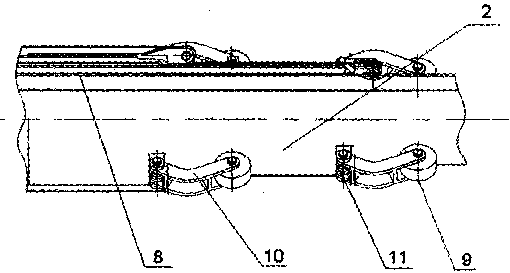
[0013] Such as figure 1 , 2 As shown in 3, the unfolding sleeve driven by the wire rope is composed of a driving part, a retractable part, a guide assembly and a locking assembly. The driving part is composed of a motor 6, a drum 7, a traction wire rope 5, a recovery wire rope 8, and a pulley 3; retractable parts It consists of three parts, namely the root sleeve 4, the middle sleeve 2 and the end sleeve 1. The guide assembly consists of the guide wheel 9, the guide wheel bracket 10 and the torsion spring 11; the locking assembly 12 is composed of a locking mechanism and a locking sensor. The end sleeve 1 is sleeved in the middle sleeve 2, and the middle sleeve 2 is sleeved in the root sleeve 4. The bottom end of the end sleeve 1, the two ends of the middle sleeve 2, and the top end of the root sleeve 4 are all installed Two sets of pulleys 3, one en...


PUM


Abstract

A wire rope driven deployment sleeve includes an end sleeve, a middle sleeve, a pulley, a root sleeve, a traction wire rope, a motor, a roller, a recovery wire rope, a guide assembly and a locking assembly. The end sleeve, the middle sleeve, and the root sleeve are set together, and two sets of pulleys are installed on the end sleeve, the middle sleeve, and the root sleeve. The traction wire rope and the recovery wire rope are wound on the drum in opposite directions. The other end of the traction wire rope is fixed on the end sleeve through the pulley on the root sleeve, the middle sleeve and the end sleeve in turn, and the other end of the recovery wire rope is directly fixed on the end sleeve, and the root sleeve and the middle sleeve are fixed on the end sleeve. Two sets of guide assemblies are installed on the top of the sleeve, and the motor is used to drive the rotation of the drum. The invention changes the moving direction of the steel wire rope and the recovery steel wire rope by changing the rotation direction of the motor, and realizes the unfolding and folding of the product. The invention has been applied to the repeatable unfolding and retracting mechanism of the flexible solar wing.

Description

Technical field [0001] The invention relates to an unfolding sleeve driven by a wire rope, which is suitable for one-dimensional linear unfolding and gathering of deployable products on a spacecraft, and can also be applied as reference in the field of civil machinery. Background technique [0002] Due to the limitation of the launch envelope of the spacecraft, many products need to be pressed on the spacecraft in the launch state, and released after the spacecraft enters orbit. As the load on the spacecraft increases, more and more such products, such as solar wings and various types of antennas, need to be equipped with corresponding deployment mechanisms. Nowadays, the commonly used unfolding mechanism of the solar wing adopts the hinge drive mechanism of the scroll spring, but it cannot be folded once it is unfolded in place. There is a spiral-driven sleeve unfolding mechanism on the antenna unfolding mechanism, but the unfolding process requires multiple motors to participat...

Claims


Application Information

Patent Timeline
IPC IPC(8): H02S30/20H01Q1/10B64G1/44
Inventor 周志清杨巧龙濮海玲吴跃民
Owner BEIJING INST OF SPACECRAFT SYST ENG
Learn More