Vacuum frying pot

A technology for vacuum frying tanks and tanks, applied in oil/fat baking, loading/unloading of ovens, etc., can solve the problems of low automation efficiency, high cost of use, and much oil accumulation at the bottom of the tank, and achieve high automation efficiency Effect

Active Publication Date: 2016-06-15
全氏食品机械(上海)有限公司
View PDF9 Cites 0 Cited by
  • Summary
  • Abstract
  • Description
  • Claims
  • Application Information

AI Technical Summary

Problems solved by technology

The disadvantages of these two structures are: 1) It is difficult to open the can lid and the basket lid, which requires manual labor and low automation efficiency; if a robot is used, the cost of

Method used


Image

  • Vacuum frying pot
  • Vacuum frying pot
  • Vacuum frying pot

Examples


Embodiment Construction

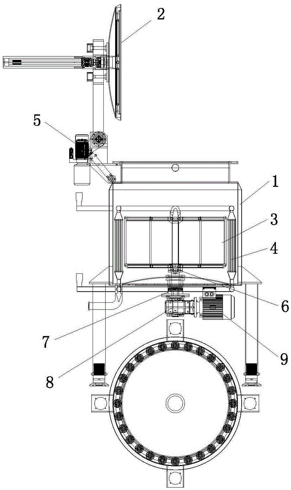
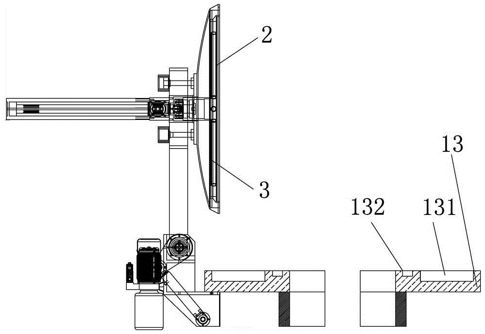
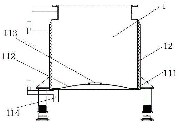
[0030] A vacuum frying tank of the present invention is composed of a tank body 1 , a tank cover 2 , a basket device 3 , a heating device 4 , an opening device 5 , a clutch 6 , a shaft coupling 7 , a reducer 8 , a motor 9 and a bracket 10 . The motor 9 and the reducer 8 are arranged under the bottom of the tank body 1 , and the motor 9 drives the material basket through the reducer 8 and the coupler 7 . The clutch 6 is composed of a guide shaft 61 and a shaft sleeve 62 , and the speed reducer 8 is fixedly connected with the guide shaft 61 of the clutch 6 .

[0031] The material basket 31 is arranged in the tank body 1, and the material basket 31 is composed of a lifting hook ear 311, an upper flange 312, a lower flange 313, a punching bottom plate 314, a punching side plate 315, and a flange fixing rod 316 , the upper and lower ends of the shaft sleeve 62 are fixed with an upper flange 312 and a lower flange 313, the lower flange is provided with a punching bottom plate 314, a...


PUM


Abstract

The invention relates to vacuum baking equipment for specific foods and particularly relates to a vacuum frying pot for foods. The invention aims at providing the vacuum frying pot. The vacuum frying pot is composed of a pot body, a pot cover, a material basket device, a heating device, a swing arm mechanism, a clutch, a coupling, a speed reducer, a motor and a fixing bracket, and is characterized in that the motor and the speed reducer are arranged at the lower surface of the bottom of the tank body and are in drive connection with each other; the clutch is composed of a guide shaft and a shaft sleeve. The vacuum frying pot has the advantages that the automation efficiency is high, and the pot cover and a material basket cover can be automatically controlled and opened.

Description

technical field [0001] The invention relates to a vacuum baking equipment for special food, in particular to a food vacuum frying tank. Background technique [0002] Chinese utility model patent ZL201320033389.0, which discloses a new type of vacuum fryer; Chinese invention patent ZL201310253159.X, double-tank vacuum fryer; double-tank is controlled by a manipulator at the same time. The disadvantages of these two structures Both are: 1) It is difficult to open the tank lid and basket lid, which requires manual labor and low automation efficiency; if a robot is used, the cost of use will be high. 2) The thermal efficiency of the steam heat exchanger is low. 3) There is a lot of oil at the bottom of the tank , There is more waste when cleaning the bottom of the tank. Contents of the invention [0003] The object of the present invention is to provide a vacuum frying tank. [0004] The present invention is achieved in this way. A vacuum frying tank is composed of a tank bo...

Claims


Application Information

Patent Timeline
IPC IPC(8): A21B5/08A21B3/07
CPCA21B3/07A21B5/08
Inventor 全武
Owner 全氏食品机械(上海)有限公司
Why Eureka
Try Eureka