Electromagnetic punching machine

A stamping machine and electromagnetic technology, which is applied in the field of electromagnetic stamping machines, can solve the problems of long production cycle, inflexible use, and many stamping machine parts, and achieve the effects of easy control, simple structure, and light weight

Inactive Publication Date: 2016-06-15
程明明
View PDF0 Cites 1 Cited by
  • Summary
  • Abstract
  • Description
  • Claims
  • Application Information

AI Technical Summary

Problems solved by technology

Therefore, this kind of stamping machine has many parts, complex structure, bulky volume, high noise, long production cycle, inflexible use, and prone to personal injury accidents

Method used


Image

  • Electromagnetic punching machine

Examples


Embodiment Construction

[0010] The following will clearly and completely describe the technical solutions in the embodiments of the present invention with reference to the drawings in the embodiments of the present invention.

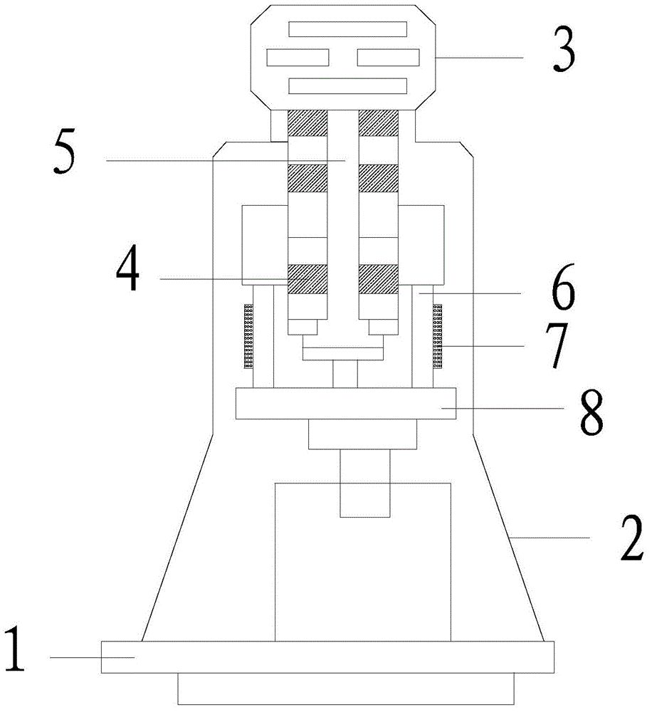
[0011] Such as figure 1 As shown, an electromagnetic stamping machine includes a workbench 1 and a body 2 arranged above the workbench 1. The body 2 is provided with a control system 3 and a linear motor in sequence. The linear motor includes a motor primary 4 and a motor secondary 5. Both sides of the motor are provided with a guide post 6 equipped with balls 7; a mold frame 8 is provided under the motor; the guide post 6 and balls 7 can ensure stamping accuracy during actual operation.

[0012] During actual implementation, plug in the power supply, start the power switch, and set the stamping tonnage. If it is automatic stamping, it is necessary to set the stamping operation frequency, and then start the stamping button, otherwise it is processed manually. When the button...


PUM


Abstract

The invention discloses an electromagnetic punching machine. The electromagnetic punching machine comprises a workbench and a machine body arranged above the workbench. The machine body is sequentially provided with a control system and a linear motor which comprises primary motor bodies and a secondary motor body. Guide posts are arranged on the two sides of the motor correspondingly, and a ball is installed in each guide post. A mould frame is arranged below the motor. The electromagnetic punching machine is simple in structure, convenient to operate, small in occupied space and stable in performance, so that not only is the production cost reduced, but also safe production can be ensured.

Description

technical field [0001] The invention relates to an electromagnetic punching machine. Background technique [0002] The power of the existing mechanical stamping machine (punching machine) comes from the rotary motor, which requires a complete set of complex conversion mechanisms to convert the rotary motion into the required linear reciprocating motion. In order to obtain sufficient punching force, it is also necessary to be equipped with an energy storage Big flywheel. Therefore, this kind of punching machine has many parts, complex structure, heavy volume, high noise, long production cycle, inflexible use, and prone to personal injury accidents. Contents of the invention [0003] In order to solve the above technical problems, the present invention provides an electromagnetic punching machine, which has a simple structure, is easy to operate, takes up less space, and has stable performance, which not only reduces production costs, but also ensures safe production. [0...

Claims


Application Information

Patent Timeline
Patent Type & Authority Applications(China)
IPC IPC(8): B30B1/42
Inventor 程明明
Owner 程明明
Why Eureka
Try Eureka