Quick passage obstacle carrying trolley
A kind of truck and fast technology, applied in the field of trucks, can solve the problems of inconvenient height adjustment of the truck, poor obstacle clearance ability, poor stability, etc., and achieve the effect of increasing steering flexibility, convenient use, and convenient operation.
- Summary
- Abstract
- Description
- Claims
- Application Information
AI Technical Summary
Problems solved by technology
Method used
Image
Examples
Embodiment 1
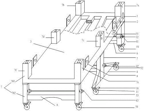
[0024] Such as figure 1 and figure 2 As shown, the fast obstacle-passing vehicle of the present invention is provided with a lifter 7, a car body 3, and universal wheels 5.
[0025] The vehicle body 3 is composed of a large frame 31 of hollow steel structure and a plate-shaped vehicle chassis 32 placed on the large frame 31 . The car body of this structure can reduce the weight of the car body as much as possible while ensuring the stability. Car body 3 is also provided with hanger nose 9, and car body both sides is symmetrically provided with two groups of hanger noses, and one group is positioned at the car body front portion, and one group is positioned at the car body rear portion, facilitates integral lifting truck.
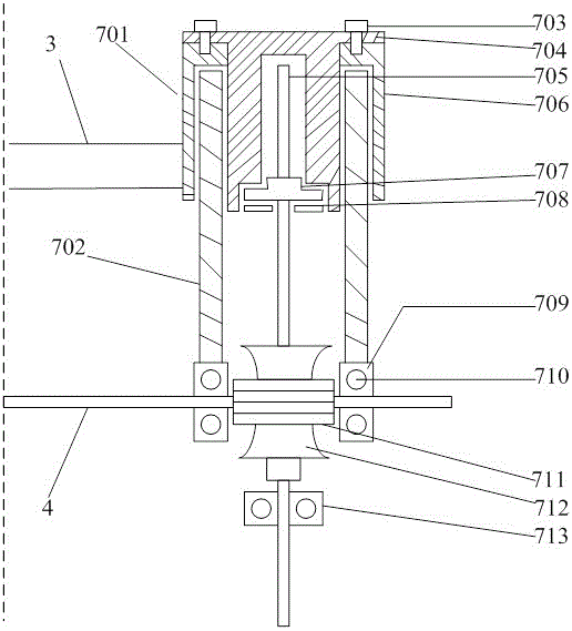
[0026] Three sets of lifters are symmetrically arranged on the left and right sides of the car body 3, and the universal wheel 3 is arranged under the lifter 7 to be linked with the lifter. The first set of lifters consists of lifter A (7a) and lifter A1...
Embodiment 2
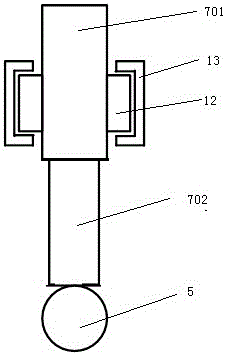
[0034] Such as image 3 As shown, in this embodiment, the position of the second group of lifters on the car body can move forward and backward, the car body is provided with a guide rail 13, and the fixing sleeve 701 of the lifter B and the lifter B1 is provided with a slide block that cooperates with the guide rail 12. The slider 12 can be welded on the fixed sleeve 701, and the slider 12 slides in the guide rail 13 to realize the movement of the upgrader, so that the position of the universal wheel 5 connected with the lifter can move forward and backward, which is convenient for adjustment according to obstacles and the second The position of the universal wheel 5 that two groups of elevators are connected. Other structures are the same as those in Embodiment 1, and will not be repeated here.
Embodiment 3
[0036] Such as Figure 4 and Figure 5 As shown, in this embodiment, a guide rail 15 is provided on the longitudinal connecting plate 8 , and a slider 14 is provided at the lower end of the telescopic arms 702 of the second group of lifters 7c, 7d, and the slider 14 slides in the guide rail 15 . This embodiment can realize the adjustment of the position of the universal wheel connected with the second group of elevators. Other structures are the same as those in Embodiment 1, and will not be repeated here.
PUM
 Abstract
Description
Claims
Application Information
 - R&D
- Intellectual Property
- Life Sciences
- Materials
- Tech Scout
- Unparalleled Data Quality
- Higher Quality Content
- 60% Fewer Hallucinations
Browse by: Latest US Patents, China's latest patents, Technical Efficacy Thesaurus, Application Domain, Technology Topic, Popular Technical Reports.
© 2025 PatSnap. All rights reserved.Legal|Privacy policy|Modern Slavery Act Transparency Statement|Sitemap|About US| Contact US: help@patsnap.com


