
Centralizer for wireline tools

Inactive Publication Date: 2006-08-15
SONDEX
View PDF24 Cites 30 Cited by
  • Summary
  • Abstract
  • Description
  • Claims
  • Application Information

AI Technical Summary

Benefits of technology

[0002]Centralizers are commonly used to support wireline tools as they are lowered or raised inside vertical, deviated or horizontally-drilled oil wells. Some tools require to be centred in order to make proper measurements or otherwise perform their intended function, and centralizers are often used to provide a smooth passage along deviated holes, including reliable entry of the tool-string when passing from a large section of borehole into a smaller section.
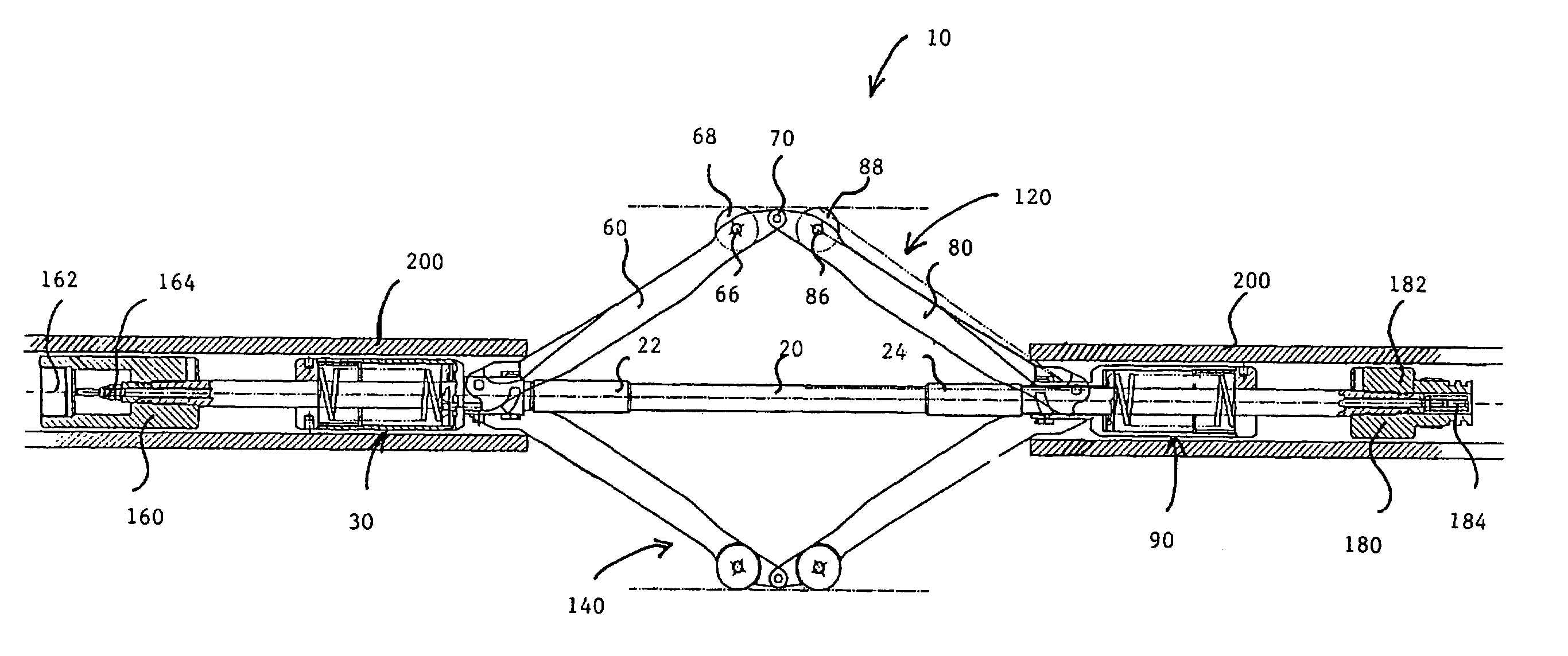
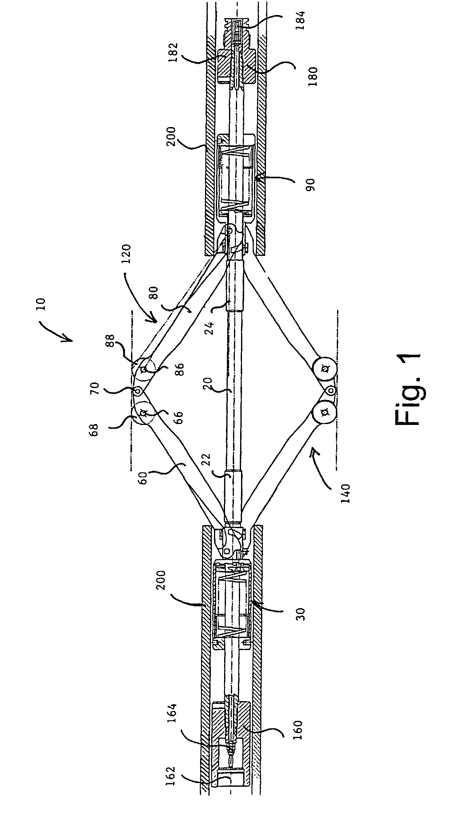
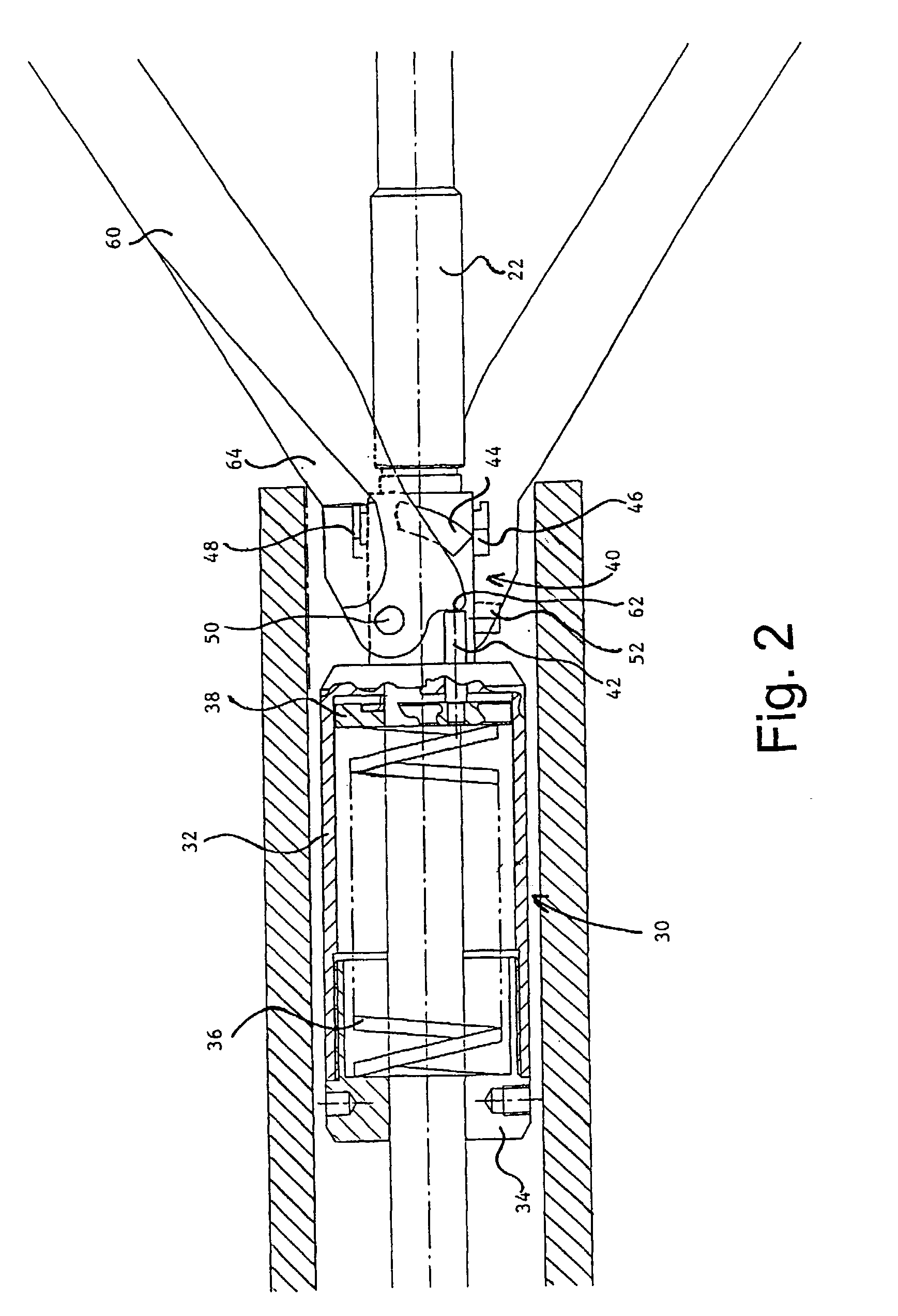
[0008]A preferred centralizer for use in oil well wireline toolstrings is described below in more detail with reference to the drawings. Briefly, the centralizer has a central mounting rod and two floating spring mechanisms, between which a number of jointed centralizer arms are connected. The jointed centralizer arms have a section with a concave profile disposed near to their pivot points, so that a closing force acting on the arms acts at a greater distance from the pivot. This has the effect of increasing the closing moment and making the centralizer easier to draw into a borehole with a narrow cross-section. The floating spring mechanisms also have a sleeve acting against the presser plate of the spring such that an axial force pulling the centralizer apparatus into a borehole is transferred directly into a force on the spring, thereby reducing the opening moment the springs exert on the centralizer arms, making them easier to close.

Problems solved by technology

Existing designs can have difficulty in entering a small borehole from a larger borehole, since the sprung assembly, which has to be powerful enough to support a heavy horizontal tool-string, has to be squeezed shut in order to pass through a narrower section of borehole.
The force which works against the sprung linkage in this way comes from the wireline or cable and is therefore limited by the maximum load that the cable can bear.
Resistance to the passage of the wireline toolstring is therefore encountered at sections of the oil well where the diameter suddenly narrows.

Method used


Image

  • Centralizer for wireline tools
  • Centralizer for wireline tools
  • Centralizer for wireline tools

Examples


Embodiment Construction

[0020]The preferred centralizer instrument 10, illustrated in FIG. 1, comprises a central mounting tool rod 20, on which floating spring mechanisms 30 and 90 are free to move between thrust transfer collars 22 and 24 and rod terminations 160 and 180 respectively.

[0021]Rod terminations 160 and 180 comprise coupling receptor 162 and electrical jack 164, and coupling jack 182 and electrical socket 184, respectively, and serve to facilitate secure physical and electrical connection of the centralizer tool to neighbouring instruments in the tool-string. Electrical connections between tools in the wireline toolstring are necessary in order to provide each tool with electrical power. Power is supplied from the surface to the toolstring via a co-axial cable which runs along the centre of the wireline itself; the electrical connections between the tools complete the circuit.

[0022]It will be understood, therefore, that terminals 160 and 180 form a complimentary receptor-connector pair which i...


PUM


Abstract

A centralizer for use in oil well wireline toolstrings comprising a central mounting rod and floating spring mechanisms between which a number of jointed centralizer arms are connected. The jointed centralizer arms have a section with a concave profile disposed near to their pivot points so that a closing force acting on the arms acts at a greater distance from the pivot, thereby increasing the closing moment and making the centralizer easier to draw into a borehole with a narrow cross-section. The floating spring mechanisms also have a linkage to the presser plate of the spring such that an axial force pulling the centralizer apparatus into a borehole is transferred directly into a force on the spring, thereby reducing the opening moment the springs exert on the centralizer arms.

Description

[0001]This invention relates to an instrument for centring wireline tools during passage through oil wells. Production logging tools, used by the oil industry, for downhole data collection, are widely known. The tools are adapted to their environment by being compact, slim and generally cylindrical in shape, so that they can fit into the narrowest boreholes and withstand the extreme pressures and rigours of the downhole environment. It is common practice to connect a number of individual tools together longitudinally to create a tool-string with a range of data collection capabilities. The tool-string is drawn through the oil borehole by a cable or wireline connected at both ends. In the case of wireline tools, the wireline is also used to supply power to the toolstring.[0002]Centralizers are commonly used to support wireline tools as they are lowered or raised inside vertical, deviated or horizontally-drilled oil wells. Some tools require to be centred in order to make proper measu...

Claims


Application Information

Patent Timeline
IPC IPC(8): E21B17/10
CPCE21B17/1021
Inventor STUART-BRUGES, WILLIAM P.SEARIGHT, THOMAS L.HARRIS, NEIL G.
Owner SONDEX
Learn More