Anchoring System for Valve Replacement

a technology of anchoring system and valve, which is applied in the field of anchoring system for valve replacement, can solve the problems of insecure fixation, the longest and slowest part of the anchoring process of the suture, and the most difficult portion of the valve replacement process, so as to simplify the cardiac valve replacement procedure and facilitate the passage of the riv

Inactive Publication Date: 2006-10-12
NOVOA ROBERTO +1
View PDF99 Cites 30 Cited by
  • Summary
  • Abstract
  • Description
  • Claims
  • Application Information

AI Technical Summary

Benefits of technology

[0007] The apparatuses and methods surrounding the present invention will simplify cardiac valve replacement procedure with a more efficient alternative of attaching a prosthetic valve. This invention involves a surgical rivet restrained by a protective sheath which aids in a smoother passage

Problems solved by technology

This manual process of knotting and securing the sutures is the longest, slowest and perhaps the most difficult portion of valve replacement.
It is particularly complicated in small aortic roots where the surgeon's fingers cannot adequately reach.
If the surgeon applies too much tension, the sutures can cut through the tissues or if the surgeon applies too little tension, the sutures are not tied down sufficiently hard resulting in insecure fixations and leaks that require repairs.
Valve replacement surgery is a long, complicated procedure taking approximately 4 hours but even longer when combined with other necessary procedures including coronary bypasses, multi-valve replacement and resection of aneurysms.
Although the time required for single valve replacement is well tolerated by patients, when the ischemic time is prolonged, myocardial dysfuncti

Method used


Image

  • Anchoring System for Valve Replacement
  • Anchoring System for Valve Replacement
  • Anchoring System for Valve Replacement

Examples


Embodiment Construction

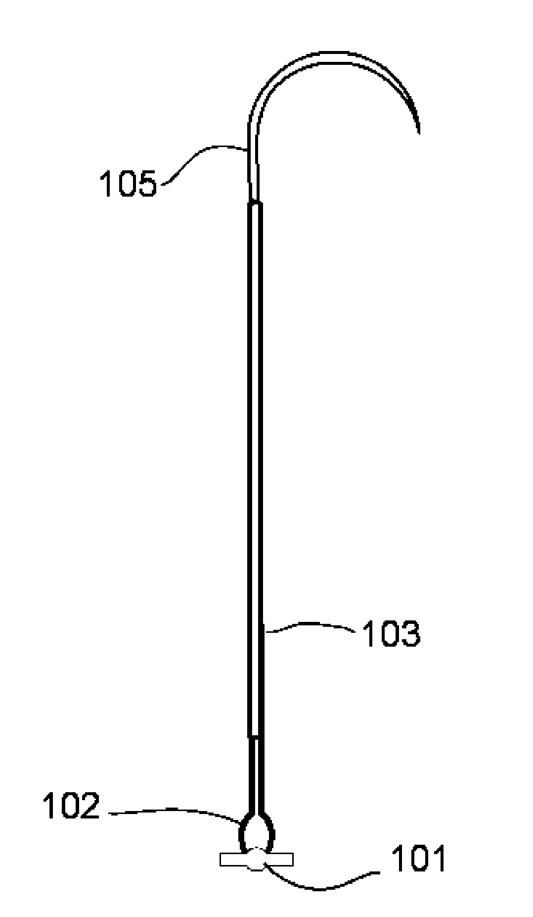
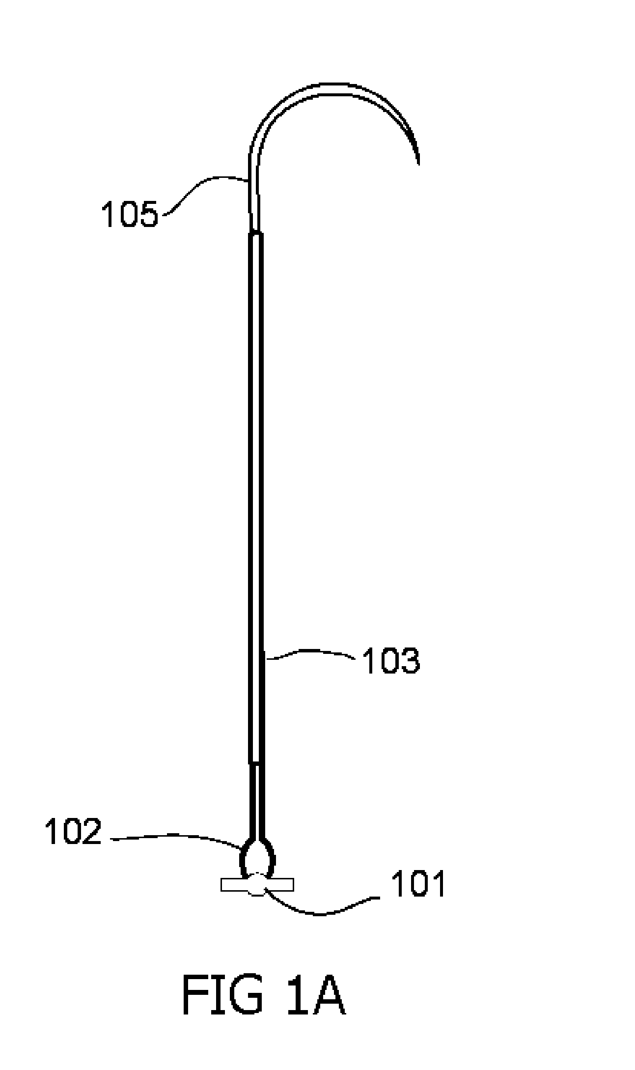
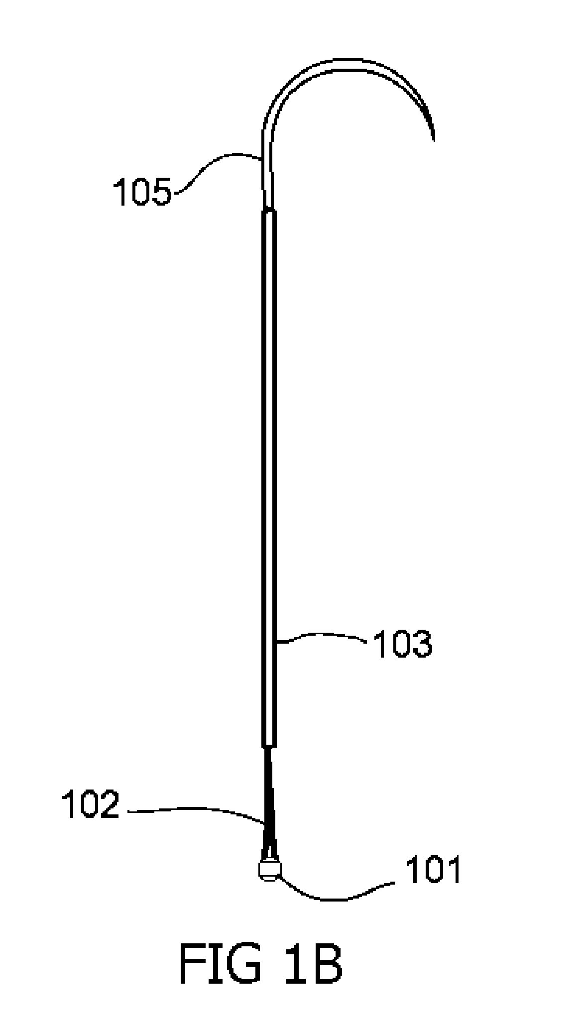
[0021] This present invention relates to apparatuses and methods for simplifying cardiac valve replacement involving a unique surgical rivet 100 shown schematically in FIGS. 1A-1B, used to attach a prosthesis sewing ring to a valvular annulus shown in FIG. 9A. The following description in conjunction with the drawings explains the details of the invention.

[0022] Referring to the drawings, and first to FIG. 1A, is the surgical rivet 100 comprise of a metallic pledget or stopper 101, two memory alloy preformed elements 102 encased in a protective sheath 103 causing the elements to be in a high tension or constrained state, attaching the memory alloy elements to a surgical needle 105. The two preformed elements 102 are wire composed of nitinol or some other memory alloy that can have a circular cross-section shown in FIG. 2A or non-circular cross-section shown in FIG. 2B to resist rotation about the elongated direction, permitting the fastener to also resist rotation. The two preforme...


PUM


Abstract

This present invention provides a surgical rivet, a rivet deployment actuator, a rivet cutting instrument and a method for securing a prosthetic valve to the heart which has the potential to substantially decrease the ischemic time required for valve implantation and allow larger prostheses to be inserted in small annuli. The surgical rivet is comprised of two flexible preformed elements capable of assuming a preconfigured shape once it is delivered and secured with the deployment actuator. The deployment actuator is a reusable instrument that lowers the prosthesis to the annulus, secures the prosthesis with an “O” ring and cuts and deploys the flexible elements so that they rest on the sewing ring of the prosthetic valve. The present invention eliminates the tedious and time-consuming tasks of tying sutures which may be particularly difficult in small annuli. It also automatically cuts the sutures to the appropriate length. The use of single rivets allows for expansion to the annulus and insertion of one full size larger (2 mm) prosthesis than what is possible using the classical horizontal pledget mattress technique. This feature is of particular importance in small annuli where prosthesis/patient mismatch can lead to suboptimal long term results. 1

Description

FIELD OF INVENTION [0001] This invention relates generally to apparatuses and methods related to cardiac valve replacement. In particular, this invention pertains to a unique surgical fastener and its method of implantation to secure a prosthetic valve to the heart structures in a more efficient and less traumatic way. BACKGROUND OF THE INVENTION [0002] When a cardiac valve malfunctions or becomes diseased and is beyond repair, the native valve is replaced with a biological or mechanical prosthesis in order to restore adequate hemodynamics. Traditionally valve replacement operations involve placing the patient on cardiopulmonary bypass, arresting the heart, removing the diseased valve leaflets and securing the prosthetic valve with sutures placed through the valve annulus. After placing the sutures through the annulus and the sewing ring of the prosthesis, the valve is lowered and each of the sutures, which may range from 12 to over 25, has to be individually tied with 4 to 6 surgic...

Claims


Application Information

Patent Timeline
IPC IPC(8): A61B17/04
CPCA61B17/0401A61B17/0469A61B17/06004A61B17/0644A61F2/2409A61B2017/0406A61B2017/0441A61B2017/0472A61B17/068
Inventor NOVOA, ROBERTODONALDSON, BENYANG, TIFFANYHUM, PHILIP
Owner NOVOA ROBERTO
Why Eureka
Try Eureka