Plastic injection mould with inner air extraction and extraction method for extracting the air carried out with said mould

a technology of injection molding and injection molds, which is applied in the field of injection molds and injection molding processes, and plastic injection molds, which can solve the problems of reducing the volume of the mold, increasing the pressure of the mold, and complicating the filling of the mold with plastic material

Active Publication Date: 2016-01-19
COMML DE UTILES Y MOLDES SA
View PDF15 Cites 0 Cited by
  • Summary
  • Abstract
  • Description
  • Claims
  • Application Information

AI Technical Summary

Benefits of technology

[0017]The injection mold of the present invention solves the problems pointed out above while at the same time constituting an efficient alternative for the complete extraction of air from the molds.
[0019]To make extracting the air from inside the cavity easier, the mold of the present invention comprises an internal circuit communicated with a vacuum pump or suction element, which will be the responsible for extracting the air from the mold cavity before and during the injection process.

Problems solved by technology

During the injection process the mold is closed and therefore the cavity is full of air which is gradually compressed as the plastic material is injected, reducing its volume and increasing its pressure, which complicates filling it with the plastic material.
In many cases, due to the temperature and pressure excess applied to the plastic material to fill the cavity, internal stresses are produced in the part itself such that the dimensional stability is lost, negatively affecting the final quality of the product.
This closing element allows removing air and closes automatically when the pressure of the injected material overcomes the pushing of the spring, thus preventing the exit of said injected material through the removal conduit, although this solution is not applicable with all materials.
These molds have several drawbacks in relation to the air removal means, the most noteworthy being that the injected material acts as a plunger pushing the air through the removal conduit, which requires greater injection pressure; and that the injected material cools more readily since it is in contact with the air, and therefore it is necessary to inject said material at a greater temperature with the subsequent energy cost.
It is necessary to invest more energy and production costs to obtain the part during the process.
Furthermore, these problems also affect the quality of the obtained part since air bubbles are trapped in the molded parts and clearances are formed in certain configurations.
The inadequate extraction of air produces grooves in the outer faces of the injected parts and during the filling of the mold the injected material is subjected to stresses which cause imperfections and deformations in the obtained parts.

Method used


Image

  • Plastic injection mould with inner air extraction and extraction method for extracting the air carried out with said mould
  • Plastic injection mould with inner air extraction and extraction method for extracting the air carried out with said mould
  • Plastic injection mould with inner air extraction and extraction method for extracting the air carried out with said mould

Examples


Embodiment Construction

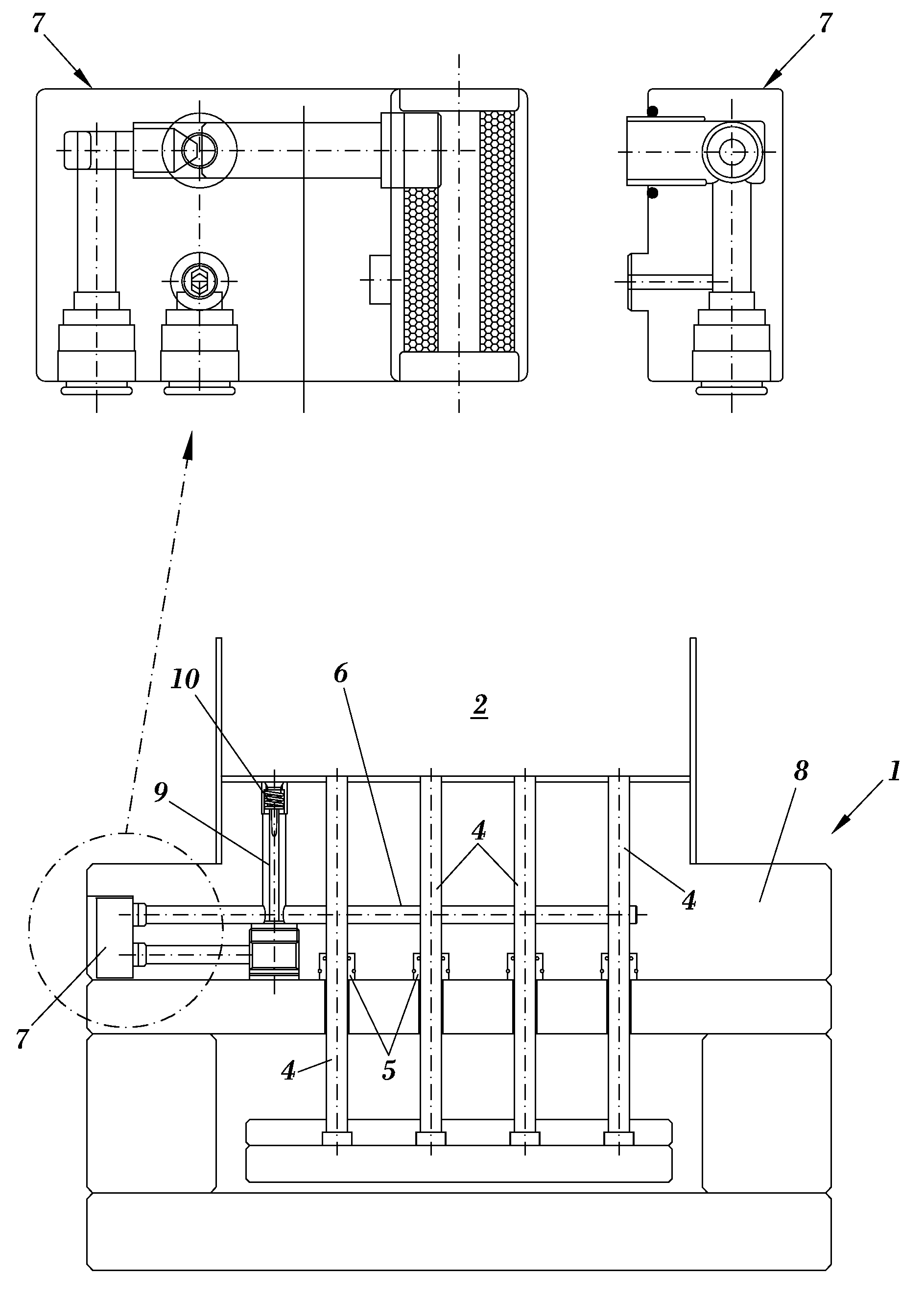
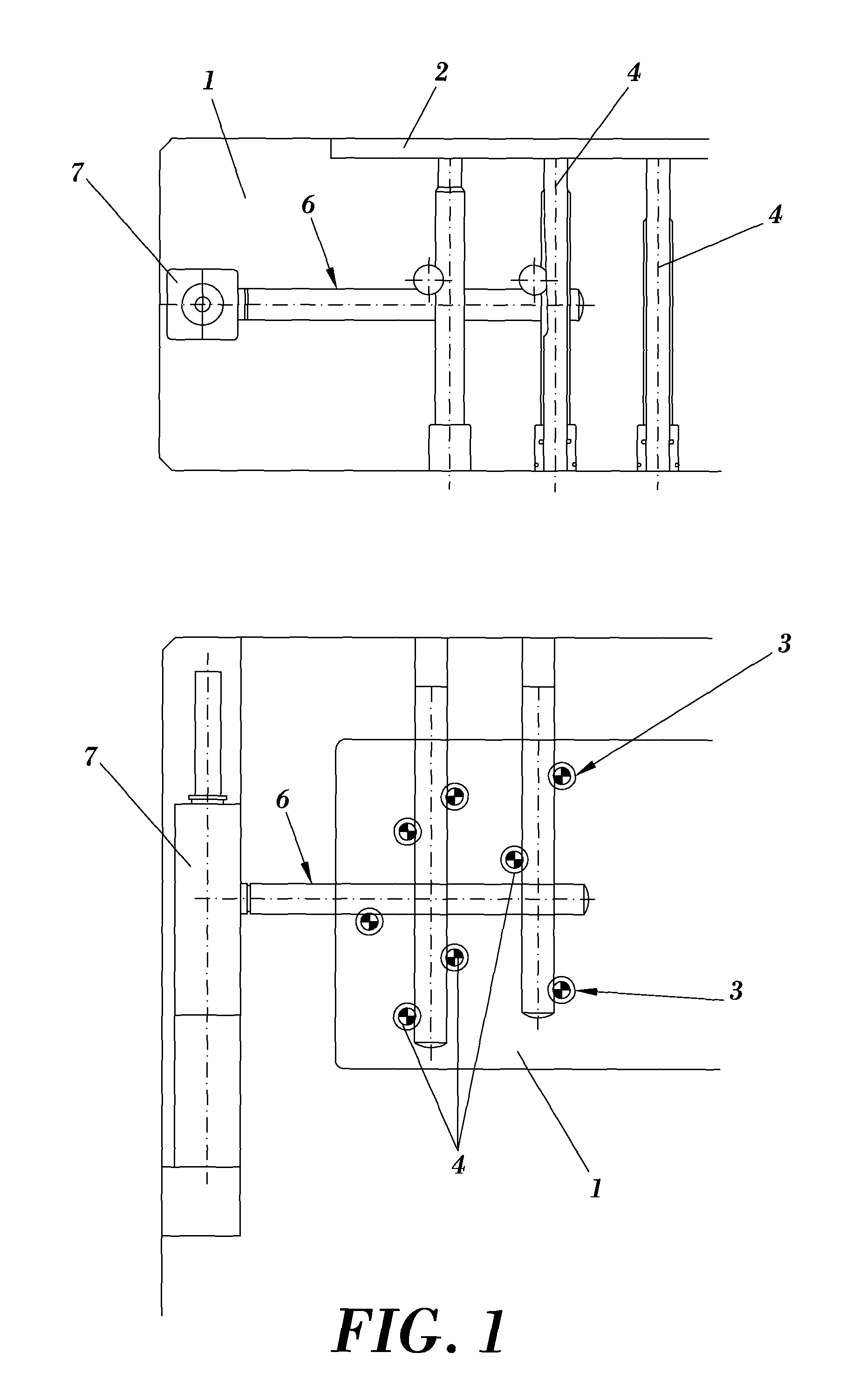
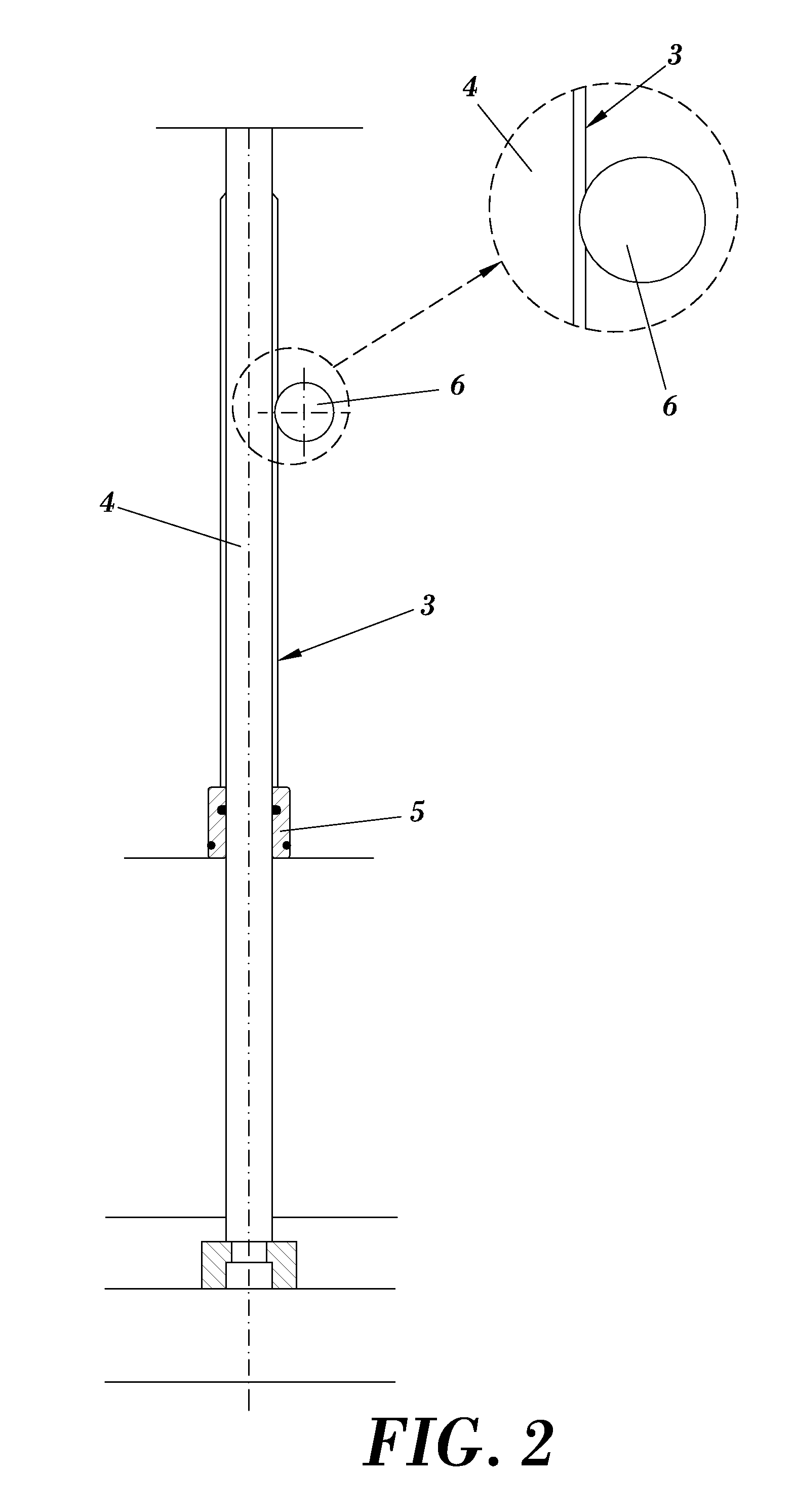
[0033]As can be seen in the figures, the injection mold (1) with inner air extraction of the present invention is structured, according to a preferred embodiment of the invention, based on closing means (not depicted), one or more injection cavities (2) provided with at least one injection nozzle (not depicted) for introducing the hot material in a liquid state and at least one ejector device for ejecting the part which is structured based on a housing (3) for an ejector pin (4) which with its movement is responsible for pushing the molded part out.

[0034]According to a preferred embodiment of the invention, the mold (1) comprises an air duct (6) connected to a vacuum pump or a suction device (7) transversely intercepting the housing (3) of the ejector pins (4) causing a suction of the air from inside the mold (1) through the existing space between the ejector pin (4) and said housing (3).

[0035]Also according to a preferred embodiment of the invention and as can be seen in the figure...


PUM

PropertyMeasurementUnit
timeaaaaaaaaaa
pressureaaaaaaaaaa
diameteraaaaaaaaaa

Abstract

A plastic injection mold which allows extracting the air from inside it during the injection process, and an extraction method, where the mold includes closing means, one or more injection cavities provided with at least one injection nozzle for introducing the hot material in a liquid state and at least one ejector device formed by a housing for an ejector pin responsible for extracting the part already molded, where an air duct connected to a vacuum pump or a suction device intercepts the housings of the ejector pins causing a suction of the air from inside the mold.

Description

TECHNICAL FIELD[0001]The present invention is applicable to the plastic material part injection molding industry, and more specifically to the sector of injecting molds and injection molding processes.[0002]More specifically, the invention concerns a plastic injection mold which allows extracting the air from inside it during the injection process and an extraction method for extracting the air using said mold.BACKGROUND OF THE INVENTION[0003]A thermoplastic injection mold is formed, among other components, by two shaping plates, one referred to as cavity plate and another referred to as die plate, as well as a set of ejector plates where several ejector pins are housed, which will serve for ejecting the injected part.[0004]An injection mold can have one or several shaping cavities, wherein at the time of injection the duly melted plastic material is introduced under pressure through an injection nozzle or point, until completely filling of each of the cavities.[0005]Each mold incor...

Claims


Application Information

Patent Timeline
Patent Type & Authority Patents(United States)
IPC IPC(8): B29C45/40B29C45/34B29C37/00
CPCB29C37/0003B29C45/34B29C45/401B29C2045/4015B29C33/40B29C45/4005B29C45/63
Inventor NAVARRA PRUNA, ALBERTODE FORTUNY PALA, JORGE
Owner COMML DE UTILES Y MOLDES SA
Why Eureka
Try Eureka