Yarn guide device of textile machine

A technology of mechanical guiding and weaving, which is applied in the directions of transportation and packaging, transportation of filamentous materials, and processing of thin materials. It can solve problems such as reducing work efficiency, increasing downtime, and falling wool, and achieves improved service life and a wide range of applications. , the effect of reducing friction

Inactive Publication Date: 2016-06-15
NINGXIA RUYI SCIENCE & TECHNOLOGY FASHION INDUSTRY CO LTD
View PDF7 Cites 3 Cited by
  • Summary
  • Abstract
  • Description
  • Claims
  • Application Information

AI Technical Summary

Problems solved by technology

[0002] The yarn guide is an important part of the textile machinery equipment. With the development of the textile industry, the types and functions of the yarn guide are also increasing. Move between to complete the weaving of gauze, and yarn guides with different apertures often need to be configured for yarns of different wire diameters, but the yarn guides in the prior art often only have yarn guide holes with one aperture, and yarns with different wire diameters The thread often needs to replace the yarn guide, which will inevitably increase the workload and labor intensity of the workers, increase the downtime, and reduce the work efficiency. After the length is reached, the end of the thread will be wound on the coil after being cut by the secant knife, which is very inconvenient to use next time, and the wool will often fall off

Method used


Image

  • Yarn guide device of textile machine
  • Yarn guide device of textile machine

Examples


Embodiment Construction

[0012] The following will clearly and completely describe the technical solutions in the embodiments of the present invention with reference to the accompanying drawings in the embodiments of the present invention. Obviously, the described embodiments are only some, not all, embodiments of the present invention. Based on the embodiments of the present invention, all other embodiments obtained by persons of ordinary skill in the art without making creative efforts belong to the protection scope of the present invention.

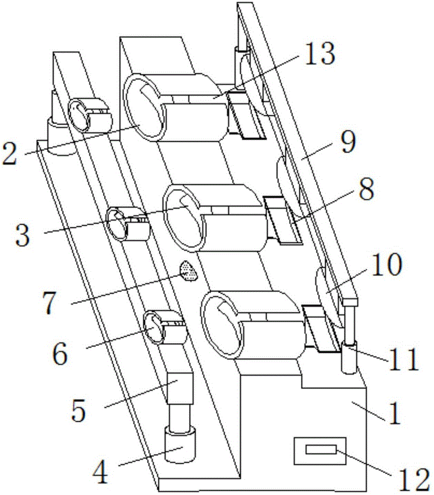
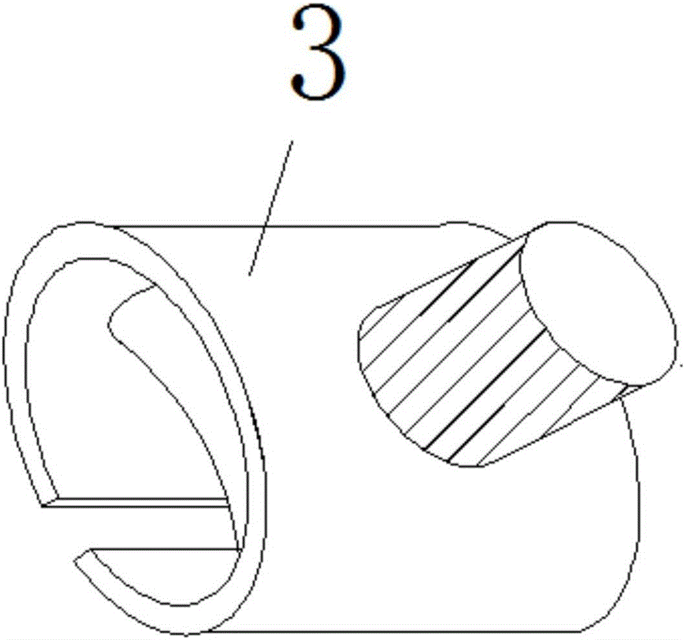
[0013] see Figure 1-2 , the present invention provides a technical solution: a yarn guide device for textile machinery, comprising a base 1, a first yarn guide hole 2 and a second yarn guide hole 6, the upper middle of the base 1 is provided with a first yarn guide hole 2 , the side of the base 1 is equipped with an infrared detector 7, the left two ends of the base 1 are respectively provided with a first telescopic rod 4, and the top of the first telescopic...


PUM


Abstract

The invention discloses a yarn guide device of a textile machine. The yarn guide device comprises a base, first yarn guide holes and second yarn guide holes. The first yarn guide holes are formed in the middle portion of the upper end of the base. An infrared detector is mounted on the side face of the base. The two ends of the left side of the base are each provided with a first telescopic rod. A fixed plate is arranged at the top ends of the first telescopic rods. The second yarn guide holes are formed in the fixed plate. A rolling shaft is arranged in each of the second yarn guide holes and the first yarn guide holes. Yarn outlets are formed in the upper ends of the second yarn guide holes and the upper ends of the first yarn guide holes. Clamping grooves are formed in the right end of the upper portion of the base. The two ends of the right side of the base are each provided with a second telescopic rod. A movable plate is arranged at the top ends of the second telescopic rods. Clamping blocks corresponding to the clamping grooves are arranged at the lower end of the movable plate. A controller is mounted in an inner cavity of the base. The service life of the yarn guide holes is prolonged, and the yarn guide device is simple in structure, high in practicality and convenient to use.

Description

technical field [0001] The invention relates to the technical field of yarn guide devices for textile machines, in particular to a yarn guide device for textile machines. Background technique [0002] The yarn guide is an important part of the textile machinery equipment. With the development of the textile industry, the types and functions of the yarn guide are also increasing. Move between to complete the weaving of gauze, and yarn guides with different apertures often need to be configured for yarns of different wire diameters, but the yarn guides in the prior art often only have yarn guide holes with one aperture, and yarns with different diameters The thread often needs to replace the yarn guide, which will inevitably increase the workload and labor intensity of the workers, increase the downtime, and reduce the work efficiency. After the length is reached, the thread end will be wound on the coil after being cut by the secant knife. It is very inconvenient to use next...

Claims


Application Information

Patent Timeline
Patent Type & Authority Applications(China)
IPC IPC(8): B65H57/06B65H57/26B65H63/00
CPCB65H57/06B65H57/26B65H63/00B65H2553/40B65H2701/31
Inventor 周盈裕
Owner NINGXIA RUYI SCIENCE & TECHNOLOGY FASHION INDUSTRY CO LTD
Why Eureka
Try Eureka