Filling valve for filing product for filling container

A filling valve and product technology, applied in bottle filling, packaging, liquid bottling, etc., can solve problems such as impossible filling and difficult filling

Active Publication Date: 2016-06-15
KRONES AG
View PDF7 Cites 5 Cited by
  • Summary
  • Abstract
  • Description
  • Claims
  • Application Information

AI Technical Summary

Problems solved by technology

In addition, it is difficult or even impossible to fill fille

Method used


Image

  • Filling valve for filing product for filling container

Examples


Embodiment Construction

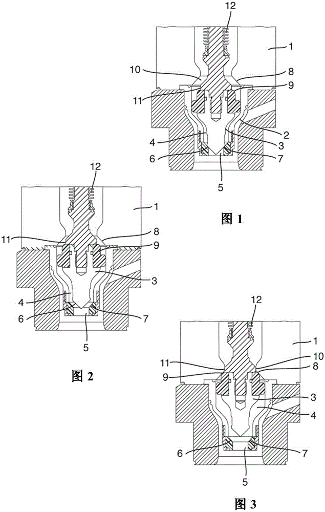
[0033] A preferred exemplary embodiment is subsequently described with reference to the drawings. Here, identical, similar or identically acting components in different drawings are denoted by the same reference numerals, and repeated descriptions of these components are partially omitted in order to avoid redundancy.

[0034] figure 1 The filling valve in is shown in cross section and has a bottom part 1 of the filling valve, a product outflow sleeve 2 and a valve cone 3 . A generally cylindrical valve cone 3 is located in the cavity of the product outlet sleeve 2 and forms an annular gap 4 through which the filling product flows to the product outlet 5 in the open valve body position. The annular gap 4 thus forms the flow path of the filling product through the filling valve.

[0035] In the region of the product outlet 5 , ie in its lower region, the valve cone 3 has a sealing contour 6 which, in the closed state, is accommodated in a corresponding complementary contour o...


PUM


Abstract

The invention relates to a filling valve for filling a container to be filled with a product to be filled, the valve having a product outlet (5) for injecting the product to be filled into the container to be filled and capable of sealingly holding Valve cone (3) in the first valve seat (7), which is moved into the first valve seat (7) by the valve cone (3) in the direction of the filling product flow towards the product outlet (5) And for shutting off the filling product flow, wherein a second valve seat (8) is provided for sealingly receiving the valve cone (3), which passes through the valve cone (3) in a direction opposite to the filling product flow direction to move into the second valve seat (8) for shutting off the filling product flow.

Description

technical field [0001] The invention relates to a filling valve for filling a container to be filled with a filling product, which filling valve is suitable for filling a plurality of product types, in particular high-viscosity and low-viscosity filling products. Background technique [0002] Filling valves for filling beverages or other liquid food products in filling installations are known in various embodiments. These filling valves usually have a valve seat and a valve cone which can be complementary to the valve seat and be accommodated in the valve seat. If the valve cone is accommodated in the valve seat, the valve cone forms an annular seal with the valve seat and closes the valve so that the filling product can no longer flow through the valve. If the valve cone is pulled out of the valve seat, the valve can be opened and the filling product can flow through the annular gap formed between the valve seat and the valve cone. In a particularly advantageous embodimen...

Claims


Application Information

Patent Timeline
IPC IPC(8): B67C3/28
CPCB67C3/28
Inventor 克里斯蒂安·布赖安东·胡贝尔
Owner KRONES AG
Why Eureka
Try Eureka