Cooling system for roller wheel

A cooling system and roller technology, applied in glass manufacturing equipment, manufacturing tools, etc., can solve problems such as abnormal use, reduced production efficiency, loss of raw materials, etc., to ensure long-term continuous work, extended service life, and reduced loss. Effect

Inactive Publication Date: 2016-06-15
JIANGYIN XINHAI ROAD CONSTR MATERIAL
View PDF0 Cites 0 Cited by
  • Summary
  • Abstract
  • Description
  • Claims
  • Application Information

AI Technical Summary

Problems solved by technology

[0002] At present, the existing rock wool machines have the following deficiencies: First, the existing rock wool machines use solid rollers. Since the rollers operate in an environment of thousands of degrees, the material on the surface of the rollers will vary with the raw materials for making rock wool. Melting and splashing together, therefore, every time a batch of rock wool is produced, the d

Method used


Image

  • Cooling system for roller wheel

Examples


Embodiment Construction

[0013] The specific implementation manners of the present invention will be further described below in conjunction with the drawings and examples. The following examples are only used to illustrate the technical solution of the present invention more clearly, but not to limit the protection scope of the present invention.

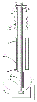
[0014] Such as figure 1 As shown, a cooling system for a roller 1 of a rock wool machine includes a roller 1 and a main shaft 2 fixedly connected to the roller 1 at one end. The roller 1 has a cavity 3 along which the main shaft 2 An inner cavity 4 communicated with the cavity 3 is opened in the axial direction, a water gun 5 is arranged in the inner cavity 4, and a rotary nozzle 6 is arranged at the end of the water gun 5, and the rotary nozzle 6 Located in the cavity 3, the size of the water gun 5 is smaller than the size of the inner cavity 4, the other end of the main shaft 2 is provided with a baffle 7, and the baffle 7 is provided with A water outle...


PUM


Abstract

The invention discloses a cooling system for roller wheels. The system comprises: a roller wheel, and a main shaft of which one end is fixedly connected to the roller wheel. The roller wheel is provided with a hollow chamber, wherein an inner chamber, being communicated with the hollow chamber, is formed in the main shaft in the axial direction. A water gun is arranged in the inner chamber. A rotary spray nozzle is arranged on one end of the water gun and is arranged in the hollow chamber. The size of the water gun is less than that of the inner chamber. A baffle plate is arranged on the other end of the main shaft. A water outlet joint is arranged at the baffle plate and is provided with a water outlet hole which is communicated with the inner chamber. The water gun sprays cooling water to cool the hollow chamber in the roller wheel, wherein the cooling water flows out from the inner chamber through the water outlet hole, thereby cooling the roller wheel. The roller wheel can work at a proper temperature always, so that surface material loss is reduced and long-time continuous work of the roller wheel is ensured and service life of the roller wheel is prolonged.

Description

technical field [0001] The invention relates to a cooling system for rollers. Background technique [0002] At present, the existing rock wool machines have the following deficiencies: First, the existing rock wool machines use solid rollers. Since the rollers operate in an environment of thousands of degrees, the material on the surface of the rollers will vary with the raw materials for making rock wool. Melting and splashing together, therefore, every time a batch of rock wool is produced, the diameter of the roller will become smaller due to melting loss, so that it cannot be used normally, and must be stopped for replacement, which not only causes the loss of raw materials, but also reduces production efficiency; second, Because the working temperature of the roller is extremely high, the roller shaft on which the roller is installed will be affected by the roller and become softened by heat. Contents of the invention [0003] The object of the present invention is t...

Claims


Application Information

Patent Timeline
IPC IPC(8): C03B37/005
Inventor 周永红
Owner JIANGYIN XINHAI ROAD CONSTR MATERIAL
Why Eureka
Try Eureka