Camera device without image displaying function

a camera device and function technology, applied in the field of camera devices, can solve the problems of inconvenient manipulation of conventional camera control techniques, inability to capture images by wireless controllers, and difficulty in simultaneously giving consideration to the buttons of master camera and slave camera by single hand operation, so as to reduce the sensitivity and accuracy of conventional mechanic buttons, the effect of simplifying the structural configuration of the camera devi

Active Publication Date: 2018-04-10
PIXART IMAGING INC
View PDF7 Cites 42 Cited by
  • Summary
  • Abstract
  • Description
  • Claims
  • Application Information

AI Technical Summary

Benefits of technology

[0012]The touch navigation module of the present invention can replace the conventional mechanic button and the conventional rotary ring, so as to simplify structural configuration of the camera device for an appearance trend of modularity and thin design. The touch navigation module utilizes optical detection, capacitance detection or radio frequency detection to detect the click amount and the shift direction of the input command, to avoid a drawback that sensitivity and accuracy of the conventional mechanic button are decreased by long-term use. Besides, the touch navigation module of the present invention reads the input command and the adjusting ring by the optical detecting technique, which has advantages of low attrition rate and great reliability of the camera device.

Problems solved by technology

Hands of the user have to respectively hold one camera, and it is difficult to simultaneously give consideration to complicated buttons of the master camera and the slave camera by single hand operation.
Manipulation of the conventional camera controlling technique is inconvenient.
The wireless controller cannot capture the image and does not provide an image displaying function.

Method used


Image

  • Camera device without image displaying function
  • Camera device without image displaying function
  • Camera device without image displaying function

Examples


first embodiment

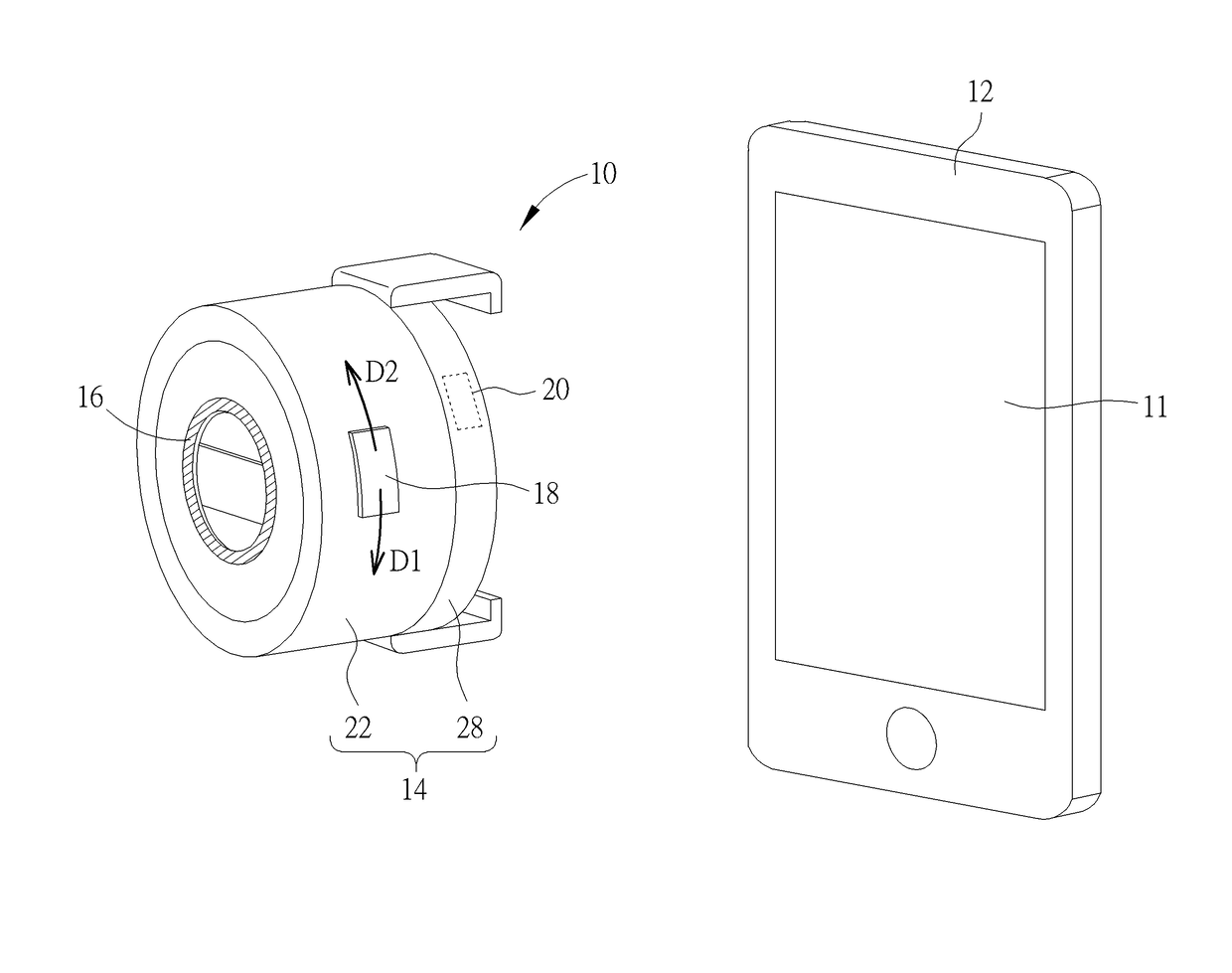
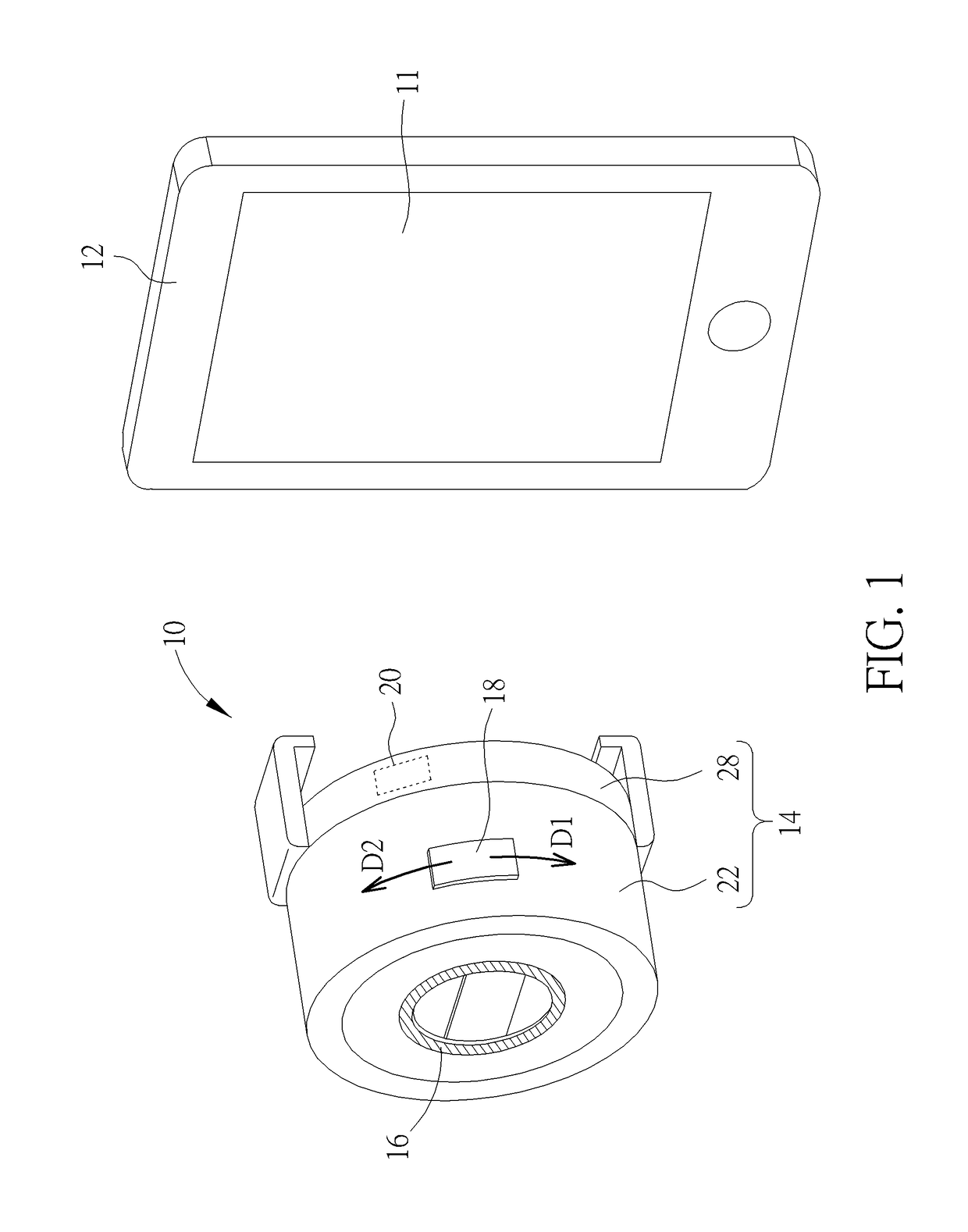
[0023]The transmission module 20 can be the WiFi communication module, the near field communication module, the radio frequency communication module and so on. Position of the transmission module 20 is not limited to the first embodiment, and depends on design demand. The portable electronic device 12 further includes a transceiver relative to the transmission module 20. The camera device 10 does not have the image displaying function, the image captured by the lens assembly 16 is transmitted to the transceiver via the transmission module 20, and displayed on the vision displaying module 11 of the portable electronic device 12. Besides, the user can input a command of taking a picture, a command of switching the adjustable mode or a command of varying the parameter by the portable electronic device 12 since the portable electronic device 12 includes a camera application program. The said command is transmitted to the transmission module 20 via the transceiver, so as to remotely cont...

third embodiment

[0027]Please refer to FIG. 5. FIG. 5 is a diagram of the camera device 10 according to the present invention. The camera device 10 can include two touch navigation modules 18 respectively disposed on opposite positions on the outer surface of the surrounding component 22. The touch navigation modules 18 are respectively adapted to detect a click command and a shift command, or each touch navigation module 18 can detect the click command and the shift command. For operating the camera device 10, two fingers are respectively put on the touch navigation modules 18 on the opposite positions of the surrounding component 22. One of the fingers (such as a thumb) can click the corresponding touch navigation module 18 to switch the adjustable mode of the lens assembly 24, and the other finger (such as a forefinger or a middle finger) can slide above the other corresponding touch navigation module 18 to vary the parameter of the adjustable mode after the intended adjustable mode is selected. ...


PUM


Abstract

A camera device without an image displaying function which is adapted to assemble with a portable electronic device with a vision displaying module is disclosed in the present invention. The camera device is electrically connected to the portable electronic device via wire / wireless connection. The camera device includes a base, a lens module and at least one touch navigation module. The base includes a surrounding component whereinside the lens module is disposed. The lens module includes a lens assembly and a digital processing unit. The touch navigation module is disposed on an outer surface of the surrounding component and electrically connected to the lens module. The touch navigation module detects an input command to trigger the lens assembly to capture an image, or controls parameters of an adjustable mode of the lens assembly via the digital processing unit.

Description

BACKGROUND OF THE INVENTION[0001]1. Field of the Invention[0002]The present invention relates to a camera device, and more particularly, to a camera device without an image displaying function and capable of utilizing a touch navigation module to vary a parameter of an adjustable mode.[0003]2. Description of the Prior Art[0004]A conventional camera controlling technique communicates a plurality of cameras by wire connection or wireless connection, and a user utilizes a control panel of one of the cameras to remotely control another camera. Each camera has a lens module and a display panel, and is able to capture an image independently. The user can input a control command by the master camera, and the control command drives the slave camera to actuate a shutter via the wire connection or the wireless connection. Each camera can be set as the master camera or the slave camera alternatively. However, the image captured by the slave camera is displayed on the display panel of the slave...

Claims


Application Information

Patent Timeline
Patent Type & Authority Patents(United States)
IPC IPC(8): H04N5/222H04N5/225H04N5/232
CPCH04N5/23216H04N5/2253H04N5/23293H04N5/23203H04N5/2254H04N23/54H04N23/66H04N23/55H04N23/62
Inventor KUO, SHIH-WEIYANG, FENG-CHENGLIU, YI-MINCHANG, YEN-MIN
Owner PIXART IMAGING INC
Why Eureka
Try Eureka