
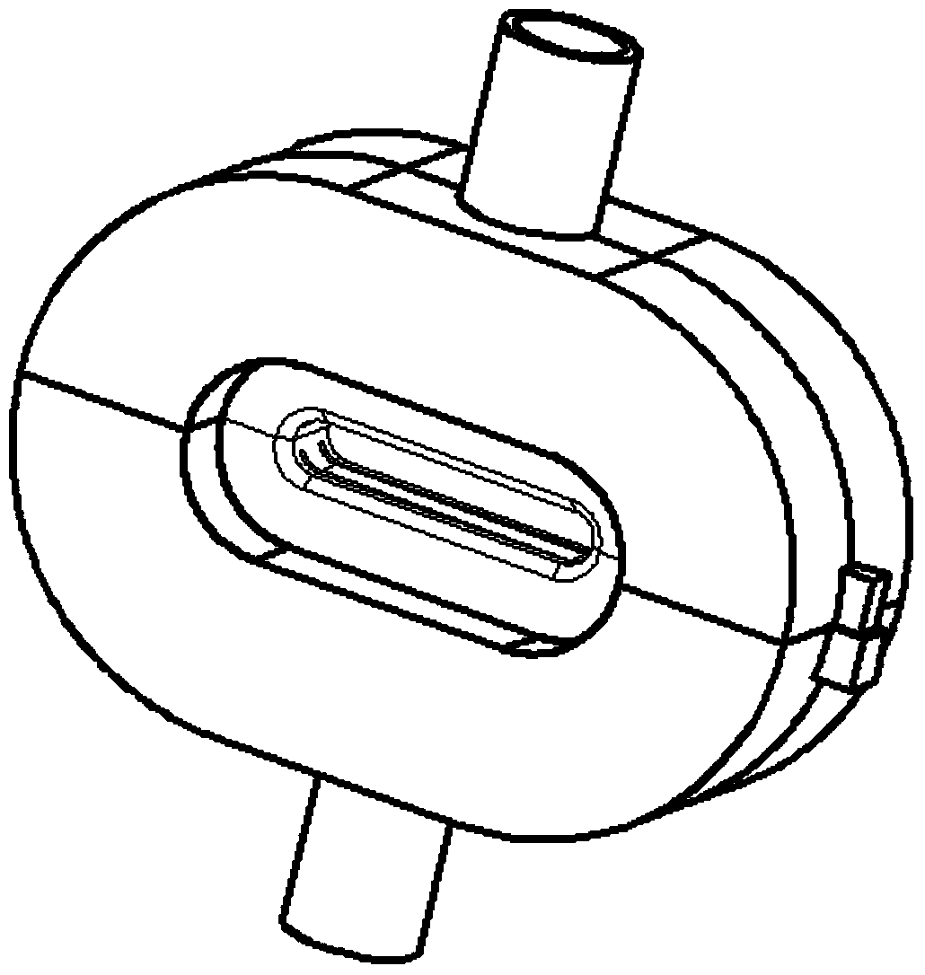
Air blowing and drying device for flat tube profiles

A drying device and flat tube type technology, which is applied in the direction of drying gas arrangement, drying, drying machine, etc., can solve the problems of difficult to maintain profiles, product quality decline, loud noise, etc.

Active Publication Date: 2018-03-16
江苏共昌精密铝业有限公司
View PDF6 Cites 0 Cited by
  • Summary
  • Abstract
  • Description
  • Claims
  • Application Information

AI Technical Summary

Problems solved by technology

[0003] The blowing drying device of the prior art has the following defects during use: because the air outlet of the device is flat, the blown wind is relatively strong and the noise is relatively large; when the pressure of the air knife blown out from the flat outlet is unstable, the profile The jitter is severe, and the profile is difficult to keep at the specified position; when the air knife directly impacts the surface of the profile, the surface moisture is scattered to the surroundings, which reduces the drying effect on the surface of the profile that has passed through the drying device; the moisture taken away by the gas flow is also will rewet the profile surface
The above factors all cause residual moisture on the surface of the profile, resulting in a decline in product quality, low yield, and increased production costs.

Method used


Image

  • Air blowing and drying device for flat tube profiles
  • Air blowing and drying device for flat tube profiles
  • Air blowing and drying device for flat tube profiles

Examples


Embodiment Construction

[0018] The present invention will be further described below in conjunction with the examples shown in the accompanying drawings.

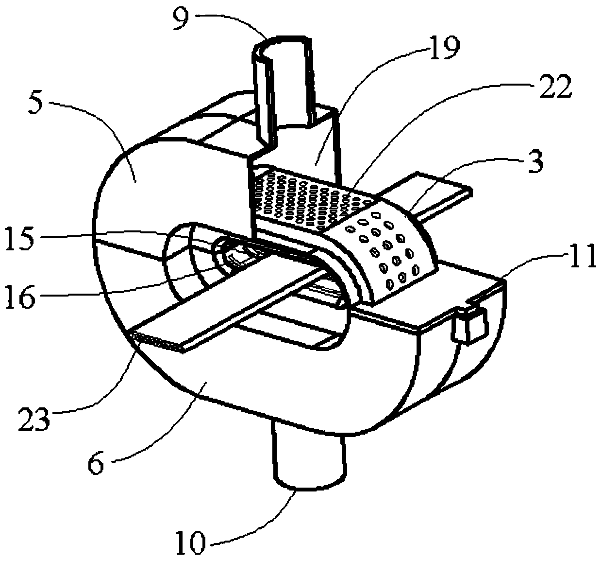
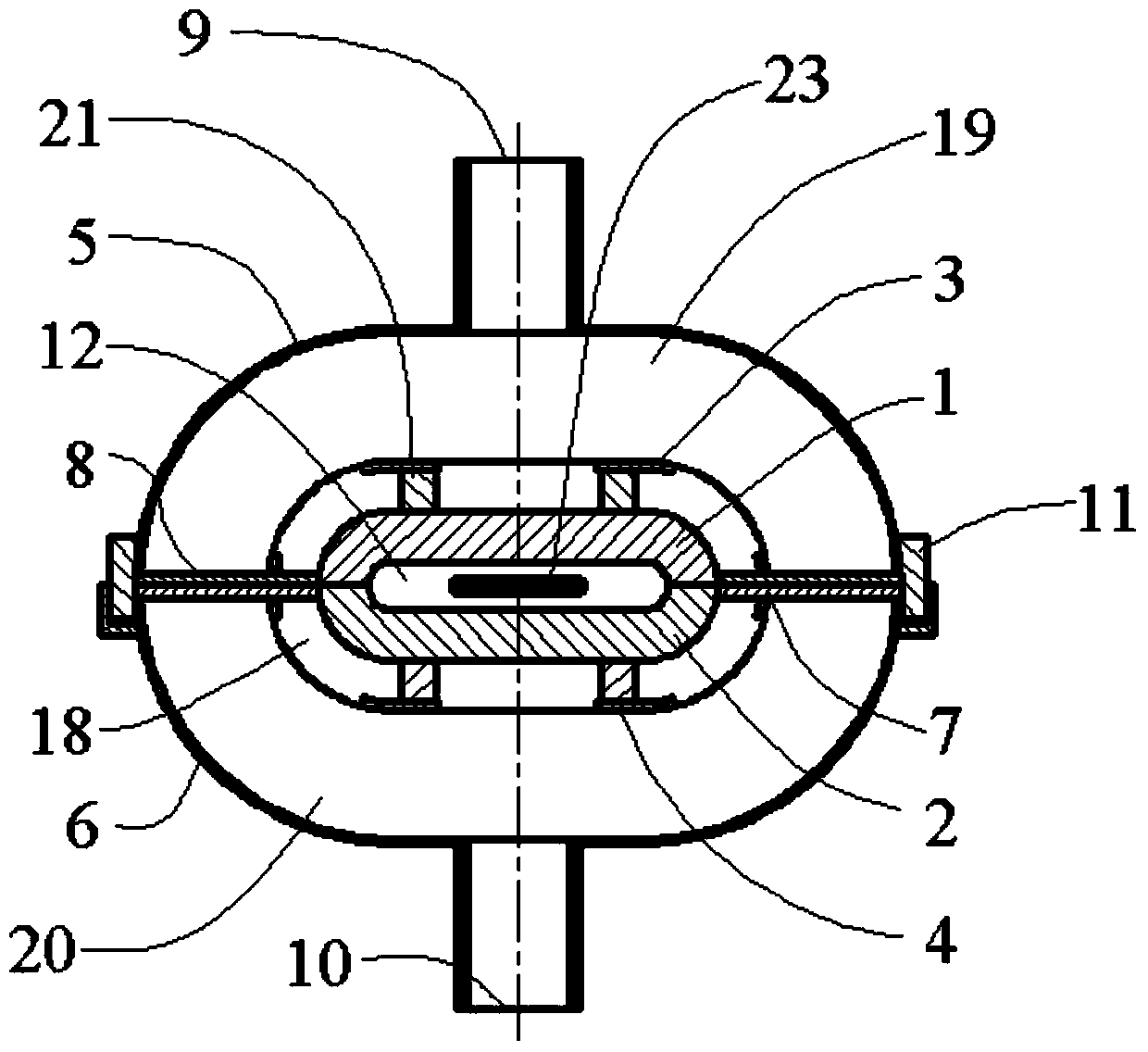
[0019] see figure 2 and image 3 , the present invention provides a blowing drying device for maintaining position stability and noise reduction function, which mainly includes inserts (1, 2), annular grooves (3, 4), shells (5, 6), partitions (7 , 8), air intake holes (9, 10) and positioning fastening components (11). Parts 1, 3, 5, 7 and 9 form the upper part of the air drying device, and parts 2, 4, 6, 8 and 10 form the lower part of the air drying device.

[0020] In the upper and lower parts of the device, the inserts (1, 2) and the annular grooves (3, 4) surround a profile pulling channel (12). Air gaps (13, 14) are provided between the insert (1) and the annular groove (3); and air gaps (15, 16) are provided between the insert (2) and the annular groove (4). The transition profile of the insert (1) at the air gap (13, 14) is rounded. I...


PUM


Abstract

The invention provides a blowing drying device for flat tube proximate matter. The blowing drying device comprises embedded parts, annular grooves, outer shells, separating parts, air inlet holes, a positioning fastening part, a traction channel, air seams, internal cavities, external cavities, a connecting piece and slotted holes; the blowing drying device is characterized in that the air seams are reserved between the embedded parts and the annular grooves; the traction channel for feeding the proximate matter is formed by the embedded parts and the annular grooves of assemblies on the upper portion and the lower portion in a surrounding manner, and the external cavities are formed by the annular grooves and the outer shells in a surrounding manner; the internal cavities between the embedded parts and the annular grooves are communicated with the external cavities through the slotted holes formed in the outer walls of the annular grooves; and the air inlet holes are formed in the outer shells. The drying device is simple in structure and convenient to install and use, can effectively blow and dry moisture on the surface of the flat tube proximate matter, can effectively keep the stable position of the proximate matter, and obviously reduces noise of blowing air knifes.

Description

technical field [0001] The invention relates to the field of special equipment for profile extrusion production, in particular to an air blowing and drying device for flat tube profiles. Background technique [0002] In the extrusion industry, the finished profile produced by the extruder generally uses an air blowing device to dry the liquid water on the surface of the profile. The air blowing device used in the existing drying link is installed at the outlet end of the cooling water tank of the extruder, or is installed in a special hot air drying box. When the produced profile passes through the drying device, the moisture on its surface is blown or dried. The drying device is convenient for all kinds of products to maintain a clean product surface, so as to realize winding in the subsequent process. [0003] The blowing drying device of the prior art has the following defects during use: because the air outlet of the device is flat, the blown wind is relatively strong ...

Claims


Application Information

Patent Timeline
Patent Type & Authority Patents(China)
IPC IPC(8): F26B21/00
CPCF26B21/004
Inventor 李凯李大永张永宁唐鼎许世峰
Owner 江苏共昌精密铝业有限公司
Learn More