
Backflow prevention components for adiabatic calorimeters

An adiabatic calorimeter and adiabatic calorimeter technology are applied in the field of backflow prevention components for adiabatic calorimeters, which can solve problems such as inability to measure heat, inability to rise in temperature, and vapor ingress, so as to reduce testing costs, control heat loss, The effect of reducing the impact

Active Publication Date: 2019-03-05
NANJING UNIV OF SCI & TECH
View PDF8 Cites 0 Cited by
  • Summary
  • Abstract
  • Description
  • Claims
  • Application Information

AI Technical Summary

Problems solved by technology

[0002] In the existing adiabatic calorimeter, which is a device for measuring the thermal hazard of substances, there is a steam reflux effect, which causes the heat of decomposition of the sample obtained in the test to be lower than the actual heat generated. This is due to the structure of the test ball used in the adiabatic calorimeter caused by
At present, the adiabatic calorimeter mainly uses two kinds of test balls. The first test ball has a diameter of 1 / 4 inch. This structure is convenient for adding samples into the test ball. However, when testing some volatile substances, due to the diameter of the test ball Larger, it will cause a large amount of steam to enter the pressure pipe, and the temperature of the pressure pipe is close to the external ambient temperature, so heat exchange occurs between the steam and the environment in the pipe, causing the steam to condense, and the condensate will re-enter the test ball along the pressure pipe, so that The temperature of the sample decreases, so that the temperature cannot rise during the test, and the heat generated by the reaction or decomposition of the substance cannot be measured; the diameter of the second test bulb is 1 / 8 inch, and this structure will reduce the amount of steam entering the pressure pipe. However, there is still a small amount of backflow liquid re-entering the test ball

Method used


Image

  • Backflow prevention components for adiabatic calorimeters

Examples


Embodiment Construction

[0014] In order to further understand the anti-reflux device for the adiabatic calorimeter, the description is as follows in conjunction with the diagram:

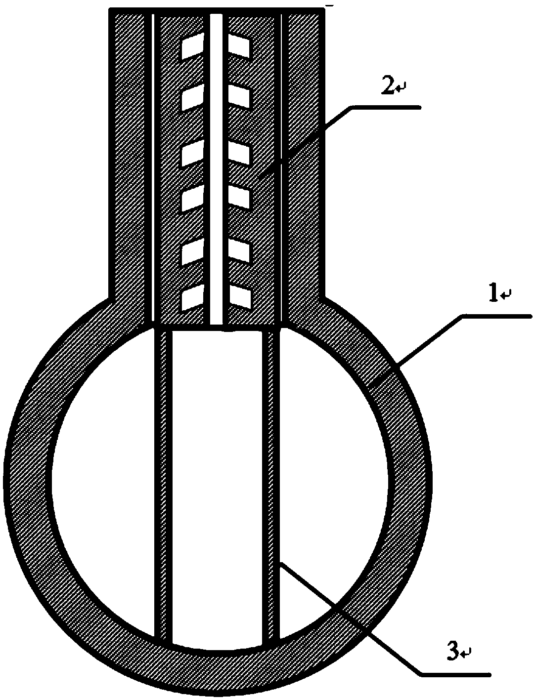
[0015] to combine figure 1 , an anti-reflux component for an adiabatic calorimeter of the present invention, a kind of anti-reflux component for an adiabatic calorimeter, the component includes an anti-reflux pipe fitting 2 and a support column 3; / 8 inches in the thermal insulation test ball 1, the anti-backflow pipe fitting 2 extends into the cavity of the thermal insulation test ball 1 through the support column 3 thereon and withstands the cavity wall.

[0016] The anti-reflux pipe fitting 2 is a cylindrical pipe, and 6-8 annular grooves at an angle of 30-60° to the pipe axis are evenly distributed in the pipe. It is used to reduce the diameter of the test bulb, store the condensate returned from the pressure pipe, and reduce the effect of steam return;

[0017] The anti-reflux pipe fitting 2 is made of 316 stainless...


PUM

PropertyMeasurementUnit
widthaaaaaaaaaa

Abstract

The invention provides a backflow preventing part for an adiabatic calorimeter. The backflow preventing part comprises an adiabatic calorimetric test ball, a backflow preventing pipe fitting and a support pillar, wherein the backflow preventing pipe fitting is mounted in the adiabatic calorimetric test ball, and the pipe diameter of the adiabatic calorimetric test ball is reduced, so that the vapor volume in a pipeline in a high temperature environment is reduced in the test process, the volume of backflow liquid is reduced, reaction heat obtained during the measurement is relatively accurate, and the testing is unlikely to be stopped due to a backflow effect; and the support pillar is fixedly connected with the backflow preventing pipe fitting and is used for supporting the backflow preventing pipe fitting. According to the backflow preventing part, a vapor backflow effect in the adiabatic calorimetric test can be effectively reduced, the production cost is low, the experiment operation is simple, the backflow preventing part can be repeatedly used, and furthermore, the testing accuracy can be improved.

Description

technical field [0001] The invention relates to an anti-reflux component for an adiabatic calorimeter, which belongs to the field of adiabatic calorimetry test. Background technique [0002] In the existing adiabatic calorimeter, which is a device for measuring the thermal hazard of substances, there is a steam reflux effect, which causes the heat of decomposition of the sample obtained in the test to be lower than the actual heat generated. This is due to the structure of the test ball used in the adiabatic calorimeter caused by. At present, the adiabatic calorimeter mainly uses two kinds of test balls. The first test ball has a diameter of 1 / 4 inch. This structure is convenient for adding samples into the test ball. However, when testing some volatile substances, due to the diameter of the test ball Larger, it will cause a large amount of steam to enter the pressure pipe, and the temperature of the pressure pipe is close to the external ambient temperature, so heat exchan...

Claims


Application Information

Patent Timeline
Patent Type & Authority Patents(China)
IPC IPC(8): G01N25/20
CPCG01N25/20
Inventor 陈利平姚亚东陈网桦
Owner NANJING UNIV OF SCI & TECH
Learn More