Fiber combining clamp for multi-channel optical fiber splitter

A multi-channel optical fiber and splitter technology, applied in the coupling of optical waveguides, light guides, optics, etc., can solve the problems of low fault tolerance, increased workload, and fiber prolapse, and achieve the goal of simplifying the operation process and increasing the fault tolerance Effect

Inactive Publication Date: 2016-06-15
蚌埠道生精密光电科技有限公司
View PDF5 Cites 3 Cited by
  • Summary
  • Abstract
  • Description
  • Claims
  • Application Information

AI Technical Summary

Problems solved by technology

[0004] After dragging the optical fiber, it is easy to cause the optical fiber to come out of the fiber holding groove, and it needs to be pressed again with the magnet head, and it is easy to touch other optical fibers during the re-tightening process, causing other optical fibers to come out, and the optical fiber needs to be readjusted, which is inefficient , and the magnet indenter directly presses on the optical fiber, which is easy to cause damage to the optical fiber, increases the workload and has a low fault tolerance rate, which is not conducive to production needs

Method used


Image

  • Fiber combining clamp for multi-channel optical fiber splitter
  • Fiber combining clamp for multi-channel optical fiber splitter
  • Fiber combining clamp for multi-channel optical fiber splitter

Examples


Embodiment Construction

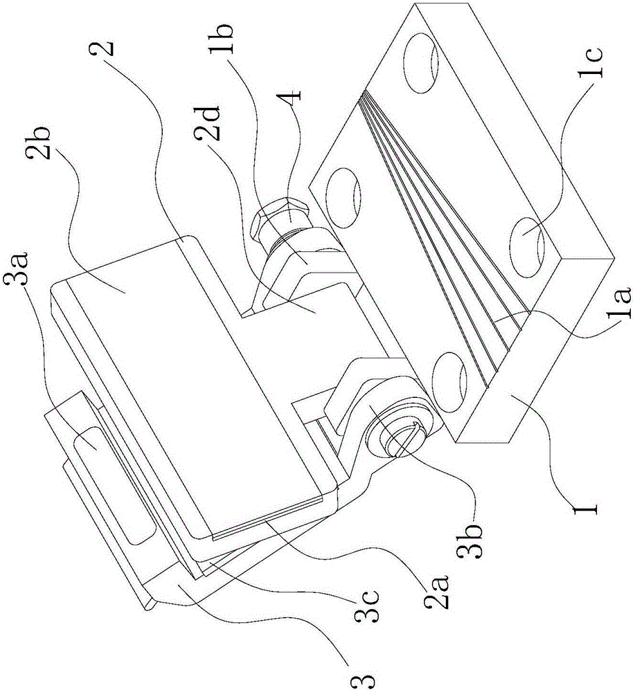
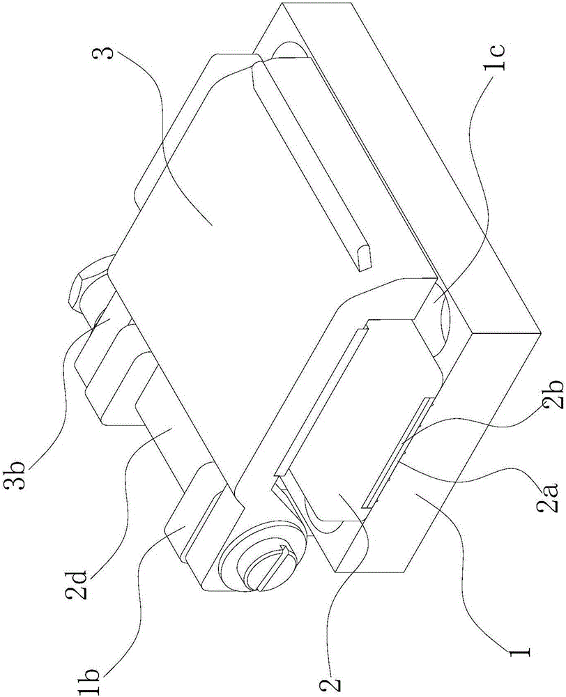
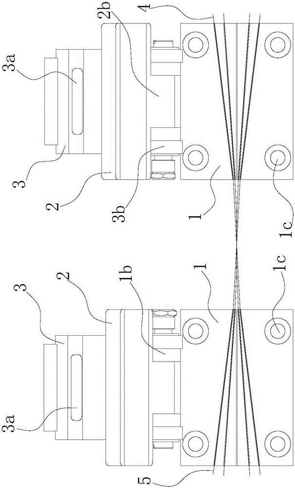
[0015] A parallel fiber fixture for multi-channel fiber splitters, such as figure 1 — image 3 As shown, it includes a metal base 1, a middle laminated fiberboard 2 and an upper laminate 3. Five optical fiber accommodation grooves 1a distributed in a radial shape and having a semicircular cross-section are evenly distributed on the upper surface of the metal base 1. The rear side of the metal base 1 has two A vertically upward ear plate 1b, pin holes are arranged on the ear plate 1b, and there are four mounting holes 1c on the four corners of the metal base 1, and the mounting holes 1c are used to fix the metal base 1 on the tapering machine;

[0016] There is a protrusion 2d in the middle on the rear side of the middle fiber laminate 2, and there is also a pin hole on the protrusion 2d. There is an inverted U-shaped groove at the bottom of the middle fiber laminate 2, and the groove can cover all the optical fiber receiving grooves 1a. There is a flexible magnet 2a in the gr...


PUM


Abstract

The invention relates to a fiber doubling fixture for a multi-channel optical fiber splitter, which comprises a metal base, a middle laminated fiber board and an upper laminated board. There are at least two optical fiber receiving grooves on the upper surface of the metal base, and the optical fiber receiving grooves are radial distribution; the middle laminated fiberboard is hinged on the back side of the metal base, and the bottom of the middle laminated fiberboard is provided with an inverted U-shaped groove, and a flexible magnet is arranged in the groove; the bottom of the upper laminated board has a compressed fiberboard receiving groove, and the pressed The accommodating groove of the fiberboard is in an inverted U shape, the rear side of the upper laminate is hinged to the metal base, and the front side is fixed with a magnetic body. The fiber doubling fixture for multi-channel optical fiber splitter of the present invention is used in conjunction with the middle laminated fiber board with a smaller magnetic force and the upper laminated board with a larger magnetic force to prevent the optical fiber from coming out of the optical fiber receiving groove during the process of artificially adjusting the optical fiber , which simplifies the operation process and increases the fault tolerance rate.

Description

technical field [0001] The invention relates to an optical fiber clamp, in particular to a fiber paralleling clamp for a multi-channel optical fiber splitter. Background technique [0002] The main function of the multi-channel fiber splitter and fiber clamp is to place the bare fiber that has been stripped of the outer protective layer in the clamp, and maintain a certain clamping state, so as to make two or more than two optical fibers close to each other, which is convenient for high temperature. The heating head is fired to achieve the purpose of fusion coupling. [0003] The existing cable clamp has at least two optical fiber accommodation grooves distributed in a radial shape on the upper surface of the metal base. In the fiber receiving groove, if the fibers are not merged together during the process of combining fibers, it is necessary to manually drag the fibers to adjust. During the dragging process, the fibers will come out of the fiber receiving grooves. The in...

Claims


Application Information

Patent Timeline
Patent Type & Authority Applications(China)
IPC IPC(8): G02B6/255
CPCG02B6/255
Inventor 严迎军康志华
Owner 蚌埠道生精密光电科技有限公司
Why Eureka
Try Eureka